
Overflow device and reservoir

An overflow device and overflow chamber technology, which is applied to water supply devices, waterway systems, drainage structures, etc., can solve the problems of the surrounding site environment and adverse effects of viewing angles, and achieve the effects of simple structure, convenient maintenance, and prevention of backflow

Active Publication Date: 2018-09-18
CHINA RAILWAY SIYUAN SURVEY & DESIGN GRP
View PDF6 Cites 0 Cited by
  • Summary
  • Abstract
  • Description
  • Claims
  • Application Information

AI Technical Summary

Problems solved by technology

[0004] In addition, in the national standard diagram, the overflow well of the reservoir has two types: 1.0m and 0.8m above the design ground, the distance between the overflow level of the clear water pool and the top of the pool is 200mm, and the thickness of the top plate of the clear water pool is about 200mm, even if the thickness of the covering soil is 500mm. , the top of the reservoir after soil covering is at least 1.2m higher than the design ground, if the thickness of the covering soil is required to be 1.0m, it is 1.7m higher than the ground, and in the cold northern region, it is more than 1.7m higher than the ground, the above reservoir and The overflow wells are at least 0.8m above the ground, which will have adverse effects on the environment and viewing angle of the surrounding sites

Method used


Image

  • Overflow device and reservoir
  • Overflow device and reservoir
  • Overflow device and reservoir

Examples


Embodiment 1

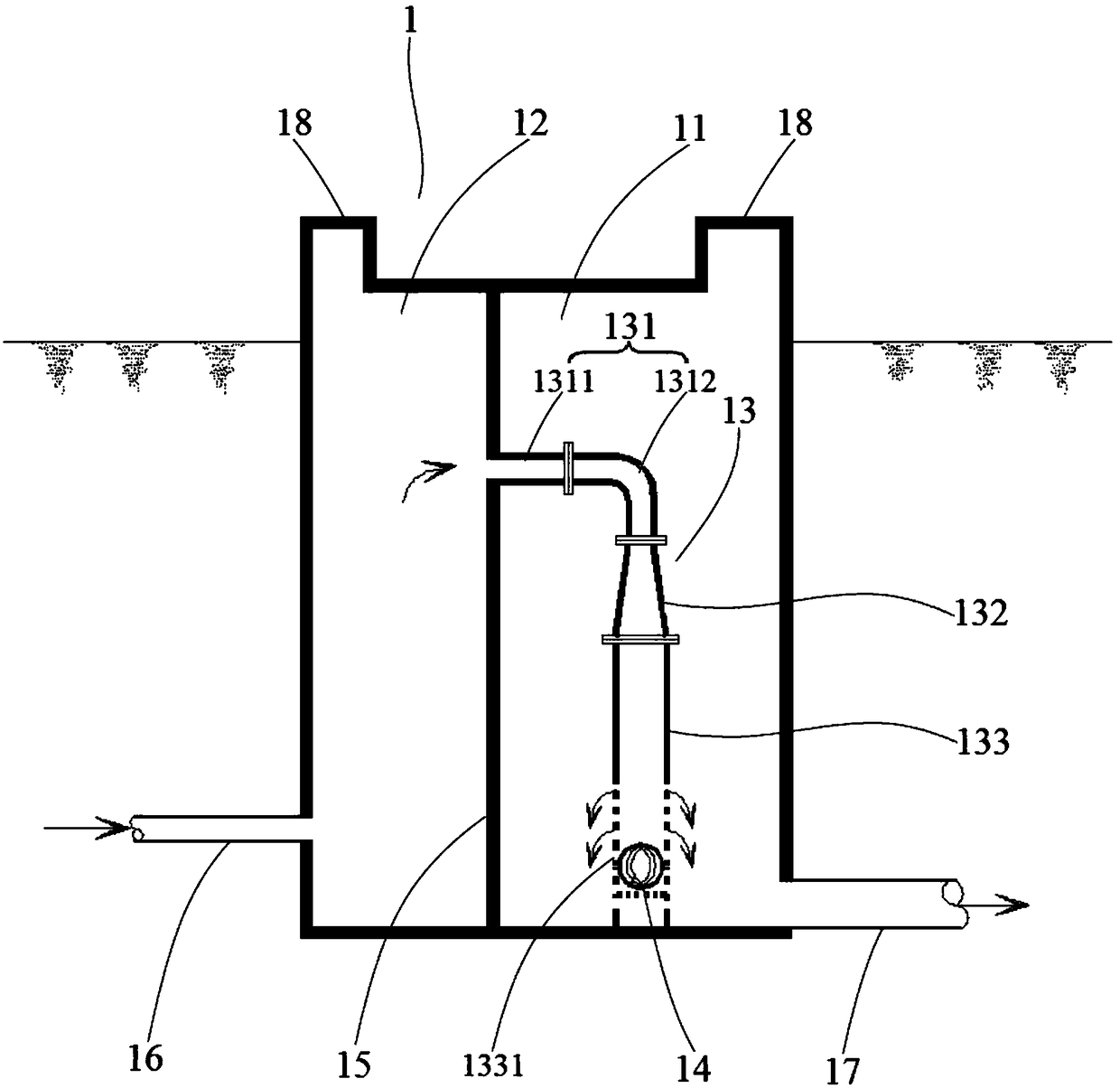
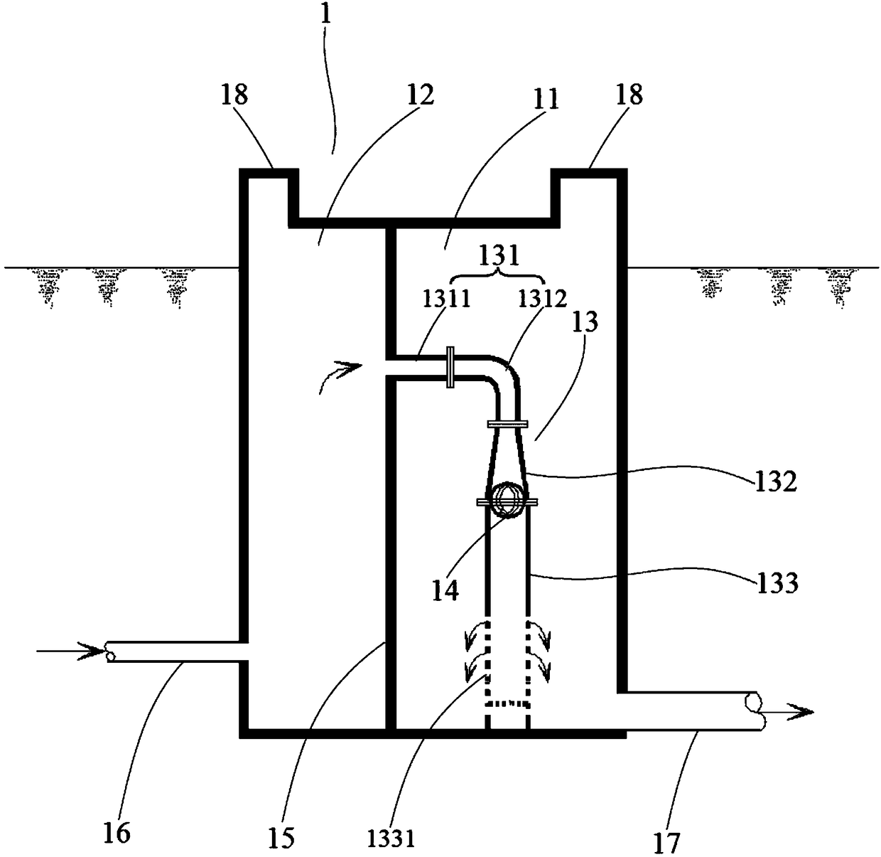
[0032] Such as Figure 1-Figure 2 , the embodiment of the present invention provides an overflow device 1, which is mainly used for the overflow of the storage tank, including an overflow chamber, and the overflow chamber is connected with a water inlet pipe 16 for introducing overflow water, and the water inlet pipe 16 is connected with the storage tank. The pool body 2 is connected. The overflow chamber includes an anti-backflow room 11, and the bottom of the anti-backflow room 11 is provided with an outlet pipe 17 for connecting with an underground drainage system; 13 includes a connection section 131, a different diameter section 132 and a water passage section 133 which are connected in sequence; The water section 133 extends and the pipe diameter gradually increases. The bottom of the water section 133 is provided with a water section 1331 for communicating with the inner space of the anti-backflow room 11. The water section 1331 is provided with a floating The floatin...

Embodiment 2

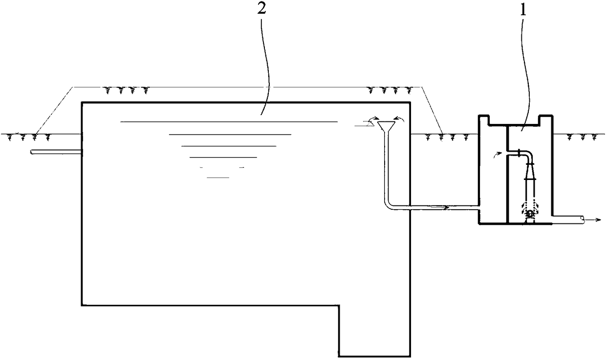
[0041] Such as image 3 , This embodiment relates to a water storage tank, including a tank body 2 and an overflow device 1, the overflow device 1 adopts the overflow device 1 provided in the first embodiment above, and its specific structure will not be repeated here. The water inlet pipe 16 communicates with the pool body 2, and the water outlet pipe 17 is connected to an underground drainage system.

[0042] Due to the anti-backflow effect and water sealing effect of the overflow device 1, the present invention is not limited by the buried depth of the pool. The overflow device 1 can be basically located below the ground, and only the manhole 18 can be left on the ground, that is: the water seal room 12 and the top of the backflow prevention room 11 are equipped with manholes 18, and the manholes 18 for two people are all located above the ground, and the overflow chamber body below the manhole 18 is all buried below the ground. Therefore, the reservoir provided in this em...


PUM


Abstract

The invention relates to an overflow device and a water reservoir provided with the overflow device. The overflow device comprises an overflow chamber, wherein an anti-backflow chamber is formed in the overflow chamber; a water outlet pipe is arranged at the bottom of the anti-backflow chamber, and a honeycomb duct is arranged inside the anti-backflow chamber; the honeycomb duct comprises a connecting section, a reducing tee section and an overflow section which are connected in sequence; the inlet end of the connecting section is communicated with the water inlet pipe; the reducing tee section extends from the connecting section to the overflow section, and the pipe diameter of the reducing tee section is gradually increased; an overflow part is arranged at the bottom of the overflow section and is used for communicating with the space in the anti-backflow chamber for overflowing; a floating ball which can float on the water surface is arranged in the overflow part, and has a diameter more than the minimum pipe diameter of the reducing tee section. By adopting the design of the anti-backflow chamber, sewage of rainwater back flowing into a pipeline can be prevented from entering the body of a water reservoir during urban inland inundation by adopting the overflow device. The overflow device does not consume electricity, has small head loss and quick drainage, can be basically buried underground, has small floor area and has small influence to surrounding landscapes.

Description

technical field [0001] The invention belongs to the technical field of water supply engineering, is applicable to water supply engineering in industries such as municipal administration, railway, electric power, and water conservancy, and specifically relates to an overflow device and a water storage tank equipped with the overflow device. Background technique [0002] The overflow pipe of the cistern is a device that must be installed in the cistern, and it is a measure to ensure the safe operation of the cistern. When the pool is full and the water intake is greater than the water output, the excess flow will be released from the overflow pipe to prevent the top plate from bearing the supporting force. The diameter of the overflow pipe is generally the same as that of the water inlet pipe, and the end of the pipe is a bell mouth, and no valve shall be installed on the pipe. In order to meet the anti-floating requirements of the reservoir, avoid direct sunlight on the top ...

Claims


Application Information

Patent Timeline
Patent Type & Authority Patents(China)
IPC IPC(8): E03F5/10E03F5/042
CPCE03F5/042E03F5/10E03F5/105
Inventor 王松林王忠合杜永新刘佳蒋金辉王婷
Owner CHINA RAILWAY SIYUAN SURVEY & DESIGN GRP
Learn More