
Low-carbon acid gas removal technique and system for high methane gas

A process method, methane-enriched technology, applied in gas fuel, petroleum industry, fuel and other directions, can solve huge environmental, industrial development disputes and restrictions, etc., to reduce atmospheric emissions, reduce construction investment and operation consumption, and economic benefits. obvious effect

Active Publication Date: 2016-10-12
重庆化工设计研究院有限公司
View PDF7 Cites 2 Cited by
  • Summary
  • Abstract
  • Description
  • Claims
  • Application Information

AI Technical Summary

Problems solved by technology

Under the background of global warming triggered by greenhouse gas emissions, although coal-to-natural gas can solve energy supply and boost economic development, it has brought huge environmental problems and industrial development. subject to controversy and restrictions

Method used


Image

  • Low-carbon acid gas removal technique and system for high methane gas
  • Low-carbon acid gas removal technique and system for high methane gas

Examples


Embodiment 1

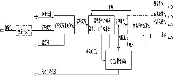
[0023] see figure 2 , the crude gas produced by SHELL waste boiler process pulverized coal gasification technology enters the shift methanation system, the temperature of the crude gas is 167°C, the pressure is 3.8MPa (A), the CO content is 70.96% (dry basis, volume), H 2 The content is 19.97% (dry basis, volume), CO 2 The content is 7.58% (dry basis, volume). The crude gas reacts in the shift methanation system to produce CO rich 2 and CH 4 The methane-enriched gas is sent to the low-carbonic gas removal system of the present invention after cooling and gas-liquid separation treatment. The temperature is controlled at about 40°C, the pressure is about 3.0MPa (A), and the CO 2 The content is 69.49% (dry basis, volume), CH 4 The content is 28.20% (dry basis, volume).

[0024] In the present invention, the methane-enriched gas is firstly cooled to about 10°C through the 1# methane-enriched gas cooler 1, and then enters the methane-enriched gas water washing tower 2, and is...

Embodiment 2

[0026] see figure 2 , the crude gas produced by GE coal-water slurry gasification technology enters the shift methanation system, the temperature of the crude gas is 242°C, the pressure is 6.5MPa (A), the CO content is 41.77% (dry basis, volume), H 2 The content is 34.81% (dry basis, volume), CO 2 The content is 22.72% (dry basis, volume). The crude gas reacts in the shift methanation system to produce CO rich 2 and CH 4 The methane-enriched gas is sent to the low-carbonic gas removal system of the present invention after cooling and gas-liquid separation treatment. The temperature is controlled at about 40°C, the pressure is about 5.5MPa (A), and the CO 2 The content is 69.32% (dry basis, volume), CH 4 The content is 29.35% (dry basis, volume).

[0027] In the present invention, the methane-enriched gas is first cooled to about 15°C by the 1# methane-enriched gas cooler 1, and then enters the methane-enriched gas water washing tower 2, and is washed with boiler feed wat...


PUM


Abstract

The invention provides a low-carbon acid gas removal technique and system for high methane gas. After raw gas is subjected to a transformation methanation reaction, the high methane gas which is rich in CH4 and CO2 is generated, and the content of CO2 exceeds 60%. The high methane gas is treated by the low-carbon acid gas removal technique provided by the invention, obtain natural gas as a product meets requirements of a kind of natural gas to the content of CO2 and the content of sulfur in the national standard GB 17,820-2012, and obtained liquid CO2 meets requirements of geological storage. The technique comprises the following steps: firstly, washing the high methane gas with water to purify the high methane gas; then cooling the high methane gas; carrying out liquid separation on most of CO2; after rectifying, super-cooling and pressurizing the separated liquid CO2, geologically storing the separated liquid CO2; carrying out low-temperature methanol washing treatment on the high methane gas after most of CO2 is separated from the high methane gas. Most of CO2 in the high methane gas is geologically stored, emission of CO2 to the atmosphere is greatly reduced, and low-carbon production is realized.

Description

technical field [0001] The invention relates to a method and system for removing methane-rich gas with low carbonic acidity, which is mainly applied to the removal and purification of acidic gas from methane-rich gas after conversion methanation treatment using raw coal gas as a raw material, and belongs to the technical field of chemical industry . Background technique [0002] my country is a country rich in coal, poor in oil, and low in gas. With the development of economy and society and the continuous improvement of urbanization rate, the demand for natural gas is gradually increasing, and the contradiction between supply and demand of natural gas cannot be fundamentally resolved in a short period of time. In order to alleviate the contradiction between supply and demand of natural gas, in areas rich in coal resources, the moderate development of coal-based natural gas is in line with the characteristics of my country's energy structure and the needs of energy consumpti...

Claims


Application Information

Patent Timeline
IPC IPC(8): C10L3/10
CPCC10L3/104
Inventor 周明灿邢挺王家天刘晋波刘静周轲刘会祯武琦
Owner 重庆化工设计研究院有限公司
Learn More