
Patsnap Eureka
For R&D, Patsnap Eureka makes reading and utilizing patents & technical documents easy.
Patsnap Eureka AIR
Designed for self-driven R&D workflows. Generate viable solutions, solve complex R&D challenges, empower your innovation with AI.

Patsnap Eureka Materials
Designed for material experts only. Revolutionize your material R&D, from search, analyze, to developing new materials.

TechResearch
Generate reliable direction feasibility study reports for your R&D in just a few steps.

TechSeek
Discover and master advanced knowledge NOW. Basics, ideas, possibilities, all at once.

TechMind
As an expert in R&D Theories, TechMind can generates customized viable solutions instantly.

TechRisk
Analyze your overall solution with one click, know your potential R&D risks in advance.

TechMonitor
Get weekly tech updates, stay abreast of the latest tech innovations and key insights.
Clamping device for tube cutting machine
A technology of clamping device and pipe cutting machine, which is applied in the direction of clamping device, positioning device, clamping, etc., can solve the problems of quality influence of pipe material cutting, vibration caused by rotation, difficulty in ensuring cutting accuracy, etc., to ensure production quality effect
- Summary
- Abstract
- Description
- Claims
- Application Information
AI Technical Summary
Problems solved by technology
Method used
Image

Examples
Embodiment Construction
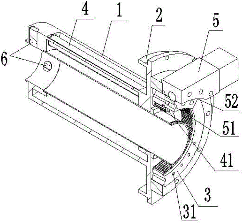
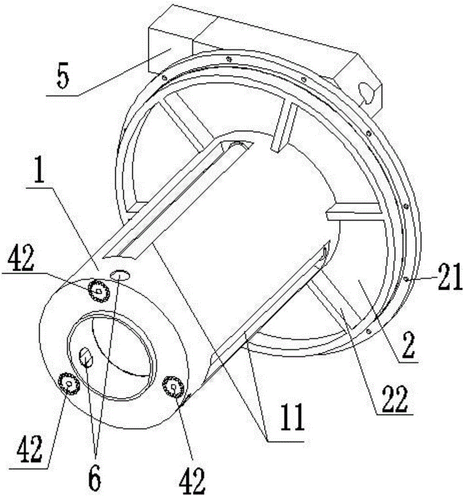
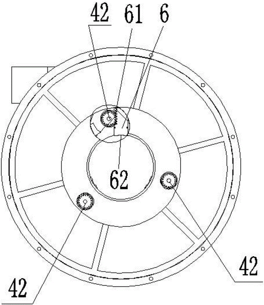
[0018] refer to Figure 1~3 , the clamping device of the pipe cutting machine, including the device shell 1, the connecting plate 2, the inner tooth rotating wheel 3, the gear transmission shaft 4, the fixing mechanism 5, and the fixing block 6, the connecting plate 2 and the device shell 1 are consolidated as a whole, and the inner The toothed rotating wheel 3 is matched and connected to the inside of the connection plate 2, the gear transmission shaft 4 is fixedly installed inside the device casing 1, the fixing mechanism 5 is connected to the connection disk 2, the fixed block 6 is placed at the tail of the device casing 1, and the gear transmission shaft 4 is mounted on both sides. The ends are meshed with the internally toothed rotating wheel 3 and the fixed block 6 respectively.
[0019] The two ends of the gear transmission shaft 4 are provided with a first gear 41 and a second gear 42. The first gear 41 is meshed with the internal tooth rotating wheel 3 and connected t...
PUM
 Abstract
Description
Claims
Application Information
 - R&D Engineer
- R&D Manager
- IP Professional
- Industry Leading Data Capabilities
- Powerful AI technology
- Patent DNA Extraction
Browse by: Latest US Patents, China's latest patents, Technical Efficacy Thesaurus, Application Domain, Technology Topic, Popular Technical Reports.
© 2024 PatSnap. All rights reserved.Legal|Privacy policy|Modern Slavery Act Transparency Statement|Sitemap|About US| Contact US: help@patsnap.com