
Device for grinding threads of screw rod and screw rod sleeve

A screw sleeve and screw technology, applied in the direction of thread cutting devices, metal processing equipment, manufacturing tools, etc., can solve the problems of low pitch accuracy, increased labor intensity, and difficult threading

Active Publication Date: 2016-10-12
YANGLI GRP CORP LTD
View PDF8 Cites 3 Cited by
  • Summary
  • Abstract
  • Description
  • Claims
  • Application Information

AI Technical Summary

Problems solved by technology

Its shortcomings are: due to the high friction between the thread grinding tool and the workpiece to be ground, it is difficult to manually pull the thread grinding tool to grind the thread of the workpiece, and the thread quality after grinding is poor, and the pitch accuracy is low. The thread is composed of two parts, the upper side and the lower side, and the workers need to grind it twice in the forward and reverse directions, which increases the labor intensity and is time-consuming and labor-intensive.

Method used


Image

  • Device for grinding threads of screw rod and screw rod sleeve
  • Device for grinding threads of screw rod and screw rod sleeve
  • Device for grinding threads of screw rod and screw rod sleeve

Examples


Embodiment Construction

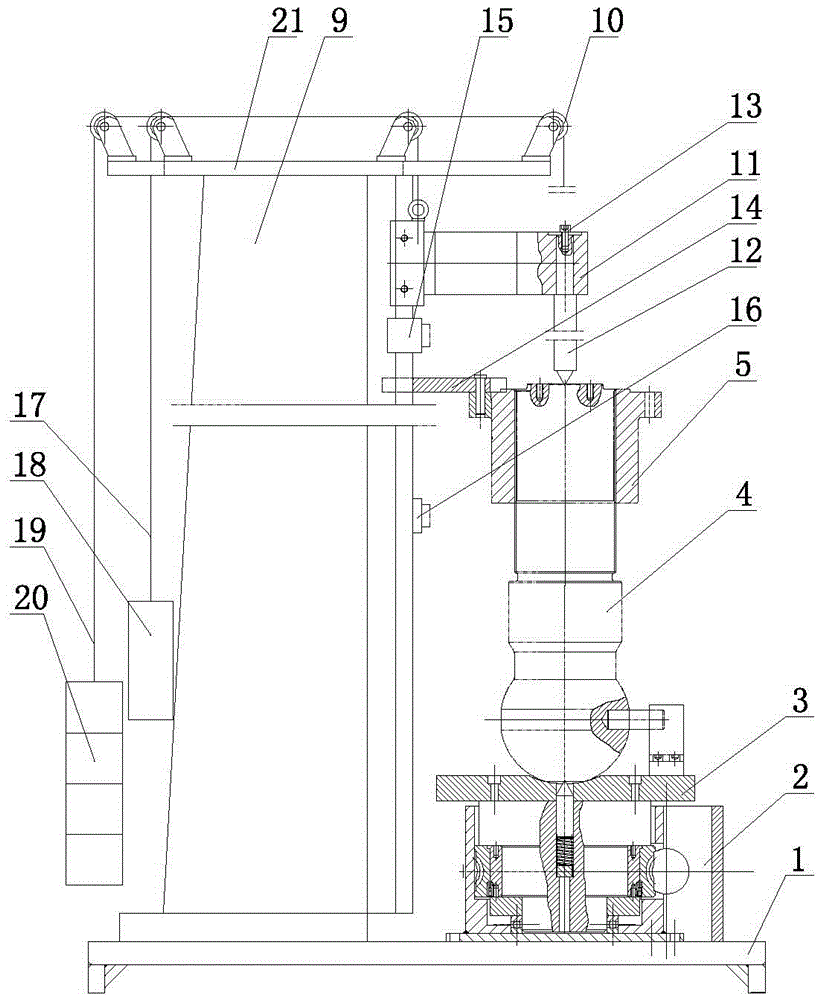
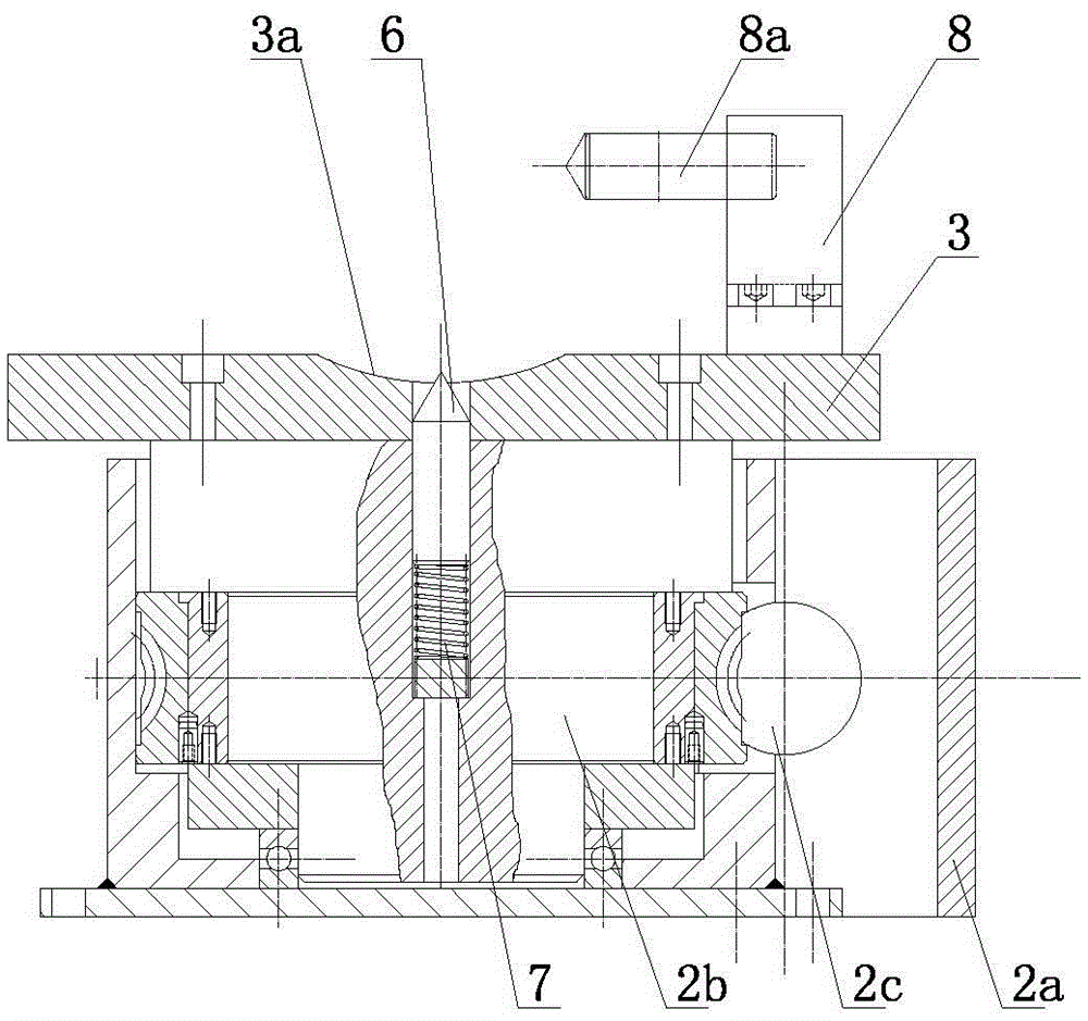
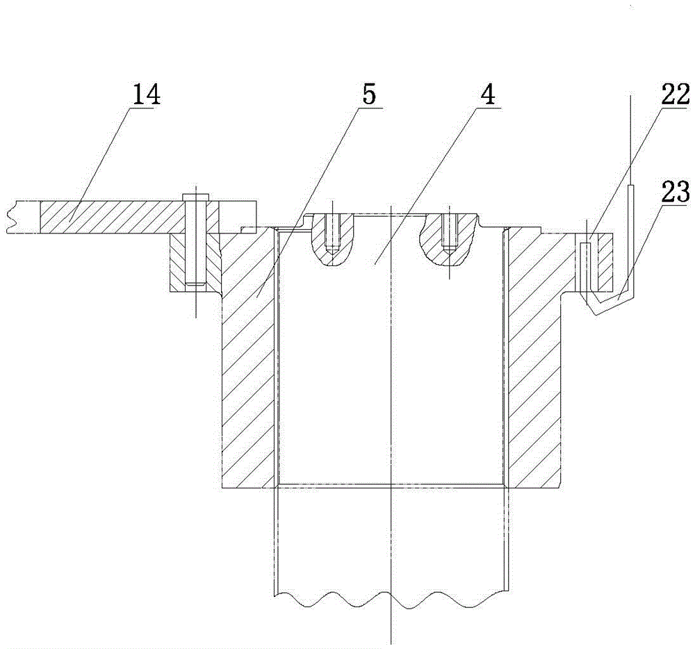
[0019] Such as Figure 1-3 Shown is a device for grinding the threads of a screw and a screw sleeve. It includes a bottom plate 1. The bottom plate 1 is provided with a rotating mechanism 2 with a rotating shaft perpendicular to the surface of the bottom plate 1. The rotating mechanism 2 is fixed to the screw sleeve 5 and the screw 4 to be ground. A horizontal positioning plate 3 is connected. The rotating mechanism is a worm gear mechanism installed in the worm gear box 2a. The positioning plate 3 is fixedly connected above the worm wheel 2b by fasteners; the middle of the positioning plate 3 is provided with the lower end of the screw 4 to be ground The matching positioning groove 3a is provided with a lower thimble 6 connected to the elastic mechanism 7 under the positioning plate 3. The lower thimble 6 passes through the positioning plate 3 and elastically abuts on the lower end of the screw 4 to be ground. The positioning plate 3 is also provided There is a locating pin se...


PUM


Abstract

The invention discloses a device for grinding threads of a screw rod and a screw rod sleeve in the field of thread machining devices. The device comprises a bottom plate. A rotating mechanism is arranged on the bottom plate. A positioning plate is connected to the rotating mechanism. A positioning groove is formed in the positioning plate. A lower centre is arranged below the positioning plate and abuts against the lower end of the screw rod. A locating pin seat is arranged on the positioning plate. A locating pin is connected to the locating pin seat. A stand column is arranged on the bottom plate. Fixed pulleys are arranged at the upper end of the stand column. A guide rail plate is connected to the stand column in a sliding manner. An upper centre is connected to the guide rail plate. The screw rod sleeve is connected with the stand column in a sliding manner. The stand column is provided with an upper limiting switch and a lower limiting switch. A connecting wrench moves vertically along the stand column. A first steel wire rope is connected to the guide rail plate. A second steel wire rope is connected to the screw rod sleeve. The end portion of the first steel wire rope is connected with a guide rail plate balancing weight, and the second steel wire rope is connected with a screw rod sleeve balancing weight. By means of the device, the thread grinding efficiency is improved, time and labor are saved, the quality of the ground threads is better, the precision of the thread pitch is higher, and the automation degree is higher.

Description

Technical field [0001] The invention belongs to the field of thread processing devices, and particularly relates to a thread grinding device. Background technique [0002] Thread refers to a spiral-shaped continuous convex portion with a specific cross-section made on the surface of a cylinder or cone. Threads are classified into triangular threads, rectangular threads, trapezoidal threads, serrated threads and other special-shaped threads according to their cross-sectional shape (tooth profile). In order to improve the thread quality and reduce the seizure and collapse of the thread during use, it is often necessary to grind the processed thread. In the prior art, people use softer materials such as cast iron to make nut-type or screw-type thread grinds, and manually perform forward and reverse rotation grinding on the parts of the machined threads on the workpiece where the thread pitch error exists, so as to improve the pitch accuracy and quench Hard internal threads are usu...

Claims


Application Information

Patent Timeline
Patent Type & Authority Applications(China)
IPC IPC(8): B23G1/36
CPCB23G1/36B23G2210/04B23G2210/08
Inventor 张锦义张杰佘宽徐跃銮徐敏花蔚
Owner YANGLI GRP CORP LTD
Learn More