
The processing procedure of the flexible processing unit of the gun sight mirror body parts

A technology of flexible processing units and processing procedures, which is applied in the direction of metal processing equipment, manufacturing tools, turning equipment, etc., can solve the problems of difficult adjustment or modification of special production lines, labor intensity of multiple operators, long production preparation cycle, etc., to improve product quality Quality and corporate image, avoiding high labor intensity, and shortening the effect of the processing process

Active Publication Date: 2018-08-14
NANTONG BAISHENG PRECISION MACHINERY
View PDF6 Cites 2 Cited by
  • Summary
  • Abstract
  • Description
  • Claims
  • Application Information

AI Technical Summary

Problems solved by technology

At present, various domestic rifle sight manufacturers organize multiple general-purpose machine tools, special-purpose machine tools or CNC machine tools to produce in the form of automatic or semi-automatic production lines according to the principle of "scattered process" when processing mirror body parts, which requires a large initial investment and relatively large investment. Long production preparation cycle, but also requires more operators and high labor intensity, and it is difficult to adjust or refit the special production line when product modification, and sometimes it is even technically impossible to achieve

Method used


Image

  • The processing procedure of the flexible processing unit of the gun sight mirror body parts
  • The processing procedure of the flexible processing unit of the gun sight mirror body parts
  • The processing procedure of the flexible processing unit of the gun sight mirror body parts

Examples


Embodiment Construction

[0020] In order to deepen the understanding of the present invention, the present invention will be further described below in conjunction with examples, which are only used to explain the present invention and do not constitute a limitation to the protection scope of the present invention.

[0021] The present invention will be further elaborated below in conjunction with accompanying drawing and embodiment:

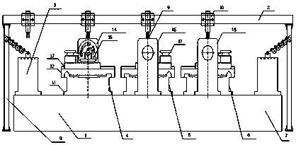
[0022] see figure 1 As shown, it is an embodiment of the processing procedure of the flexible processing unit of the rifle scope mirror body part of the present invention. The flexible processing unit of the rifle scope mirror body part includes a base 1, a column 8, and a truss 2, and the truss 2 is provided with a plurality of belts. The material trolley 10 of the mechanical claw 9, the base 1 is provided with the feeding table 3, the No. 1 station table 4, the No. 2 station table 5, the No. 3 station table 6, and the discharge Workbench 7, No. 1 station workbench 4 ...


PUM


Abstract

The invention discloses a flexible machining unit applied to gun aiming lens barrel parts. The flexible machining unit applied to gun aiming lens barrel parts comprises a base, stand columns and a truss, wherein a plurality of material trolleys with mechanical claws are arranged on the truss; a feeding worktable, a first station worktable, a second station worktable, a third station worktable and a discharging worktable are successively arranged on the base from left to right; a station main shaft box and a hook-shaped pressing plate are arranged on the first station worktable; a second station main shaft box and a square cutter frame are arranged on the second station worktable; a third station main shaft box is arranged on the third station worktable; a bed body, a large dragging plate and an upper dragging plate are arranged on the base of each of the first station worktable, the second station worktable and the third station worktable; the hook-shaped pressing plate is mounted on the upper dragging plate on the first station worktable; the square cutter frame is mounted on the upper dragging plate on the second station worktable. The flexible machining unit applied to the gun aiming lens barrel parts has the advantages of high automation degree, high machining accuracy, high working efficiency, convenience in operation, safety, reliability and low labor strength.

Description

technical field [0001] The invention relates to a processing procedure of a flexible processing unit of a gun sight mirror body part. Background technique [0002] The flexible processing unit has the characteristics of realizing the flexibility and automation of a single machine and adapting to the processing of various products, and has entered the stage of popular application so far. The flexible processing unit for gun sight body parts is developed for gun sight accessories processing enterprises. Its main function is to adjust the gun sight body of different specifications with small investment and short cycle to achieve flexible, universal and applicable products. Frequently changing "flexible" processing units. At present, when processing mirror body parts, various domestic rifle sight manufacturers organize multiple general-purpose machine tools, special-purpose machine tools or CNC machine tools to produce in the form of automatic or semi-automatic production lines...

Claims


Application Information

Patent Timeline
Patent Type & Authority Patents(China)
IPC IPC(8): B23B3/36
CPCB23B3/36
Inventor 沈伟平
Owner NANTONG BAISHENG PRECISION MACHINERY
Learn More