air handling system

An air treatment system and space technology, applied in air conditioning system, space heating and ventilation, space heating and ventilation details, etc., can solve the problems of low processing efficiency, large air, etc., to improve processing efficiency, reduce complexity, The effect of reducing the number

Active Publication Date: 2019-04-09
S Y TECH ENG & CONSTR CO LTD +1
View PDF9 Cites 1 Cited by
  • Summary
  • Abstract
  • Description
  • Claims
  • Application Information

AI Technical Summary

Problems solved by technology

[0004] The invention provides an air treatment system, which solves the technical problems in the prior art that all the circulating air in a clean room is treated by a chemical substance pollutant treatment device, resulting in a huge amount of air to be treated and low treatment efficiency

Method used


Image

  • air handling system
  • air handling system
  • air handling system

Examples


Embodiment Construction

[0039] The following will clearly and completely describe the technical solutions in the embodiments of the present invention with reference to the accompanying drawings in the embodiments of the present invention. Obviously, the described embodiments are only some, not all, embodiments of the present invention. Based on the embodiments of the present invention, all other embodiments obtained by persons of ordinary skill in the art without making creative efforts belong to the protection scope of the present invention.

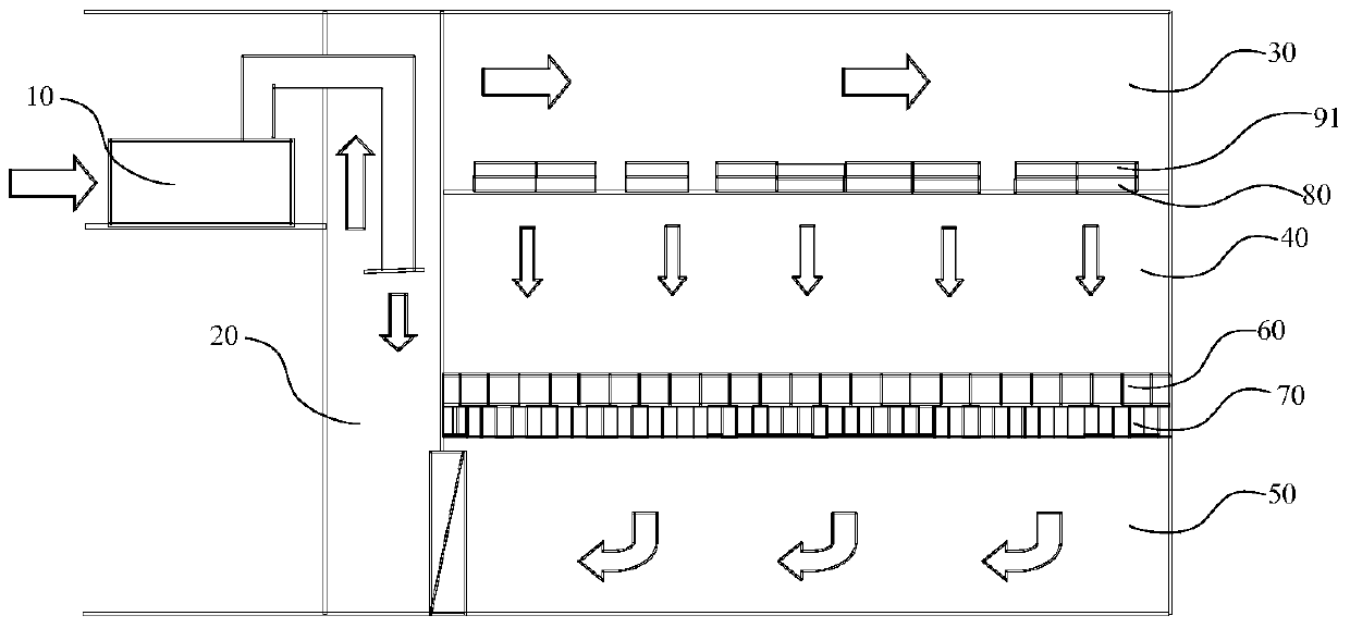
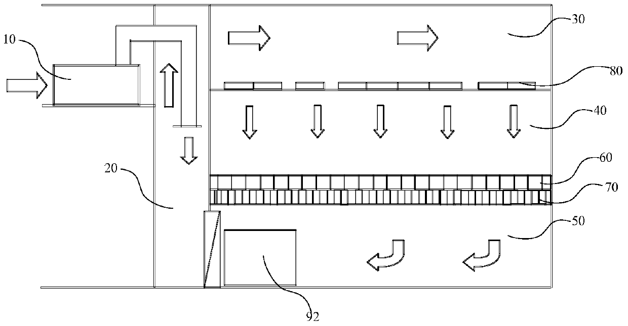
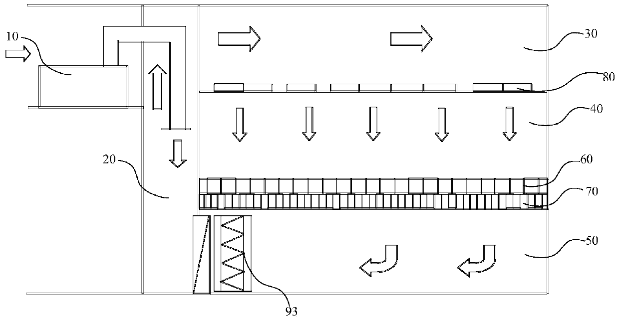
[0040] The air treatment system of an embodiment of the present invention, such as Figure 5 As shown, it includes a clean room 100, an upper interlayer 200, a lower interlayer 300, and a return air shaft 400 respectively located above and below it; the clean room 100 includes an equipment enclosure 110 extending from the top of the clean room to the bottom, The space surrounded by the equipment enclosure 110 is used to accommodate equipment that emits chemica...


PUM


Abstract

The invention discloses an air treatment system. The air treatment system comprises a clean room, an upper interlayer, a lower interlayer and an air-returning shaft, wherein the upper interlayer is located on the clean room, and the lower interlayer is located under the clean room; equipment fences are arranged inside the clean room, and space defined by the equipment fences is used for containing equipment generating chemical substance pollutants in the work process; the lower interlayer and the clean room are separated by a separation plate system with an air return port; lower-layer fences extending to the bottom from the top of the lower interlayer are arranged inside the lower interlayer, and air inside the equipment fences can enter the lower-layer fences from the air return port of the separation plate system; a chemical substance pollutant treatment device located inside the lower interlayer communicates with the space defined by the lower-layer fences through a pipeline; air treated by the chemical substance pollutant treatment device can enter the upper interlayer through the air-returning shaft. According to the air treatment system, the technical problems that because circulating air inside the clean room needs to be completely treated by the chemical substance pollutant treatment device, the amount of the air to be treated is huge and the treatment efficiency is low are solved.

Description

technical field [0001] The invention relates to the technical field of air filtration and treatment, in particular to an air treatment system. Background technique [0002] At present, some high-tech production plants at home and abroad have strict requirements on trace chemical substances in the indoor air, air temperature and humidity, and cleanliness due to their precision and fine processing requirements. Therefore, in such projects that have been built or are under construction at home and abroad, in order to control the trace chemical substances in the clean room, it is necessary to treat the chemical substances in the fresh air and the circulating air in the clean room separately. [0003] Figure 1-Figure 4 is a schematic diagram of an existing air handling system such as Figure 1-Figure 4 As shown, the existing air handling system includes a fresh air handling unit 10, a return air shaft 20, an upper mezzanine 30, a clean room 40, a lower mezzanine 50, a raised flo...

Claims


Application Information

Patent Timeline
Patent Type & Authority Patents(China)
IPC IPC(8): F24F3/16F24F13/28
Inventor 秦学礼郑伊文黄文胜恽飞李鹏余少晖肖红梅李卫
Owner S Y TECH ENG & CONSTR CO LTD
Why Eureka
Try Eureka