Z-pinching load structure with positive polarity radial electric field

A technology of radial electric field and load structure, applied in the direction of electrical components, plasma, etc., can solve the problems of insufficient energy deposition of metal wires, etc., and achieve the effects of weakening adverse effects, slowing down the formation, and increasing the time of ohmic heating

Inactive Publication Date: 2016-09-28
NORTHWEST INST OF NUCLEAR TECH
View PDF6 Cites 3 Cited by
  • Summary
  • Abstract
  • Description
  • Claims
  • Application Information

AI Technical Summary

Problems solved by technology

[0003] The purpose of the present invention is to provide a Z-pinch load structure with a positive radial electric field, which can ch

Method used


Image

  • Z-pinching load structure with positive polarity radial electric field
  • Z-pinching load structure with positive polarity radial electric field
  • Z-pinching load structure with positive polarity radial electric field

Examples


Embodiment Construction

[0019] The present invention will be described in detail below in conjunction with the accompanying drawings.

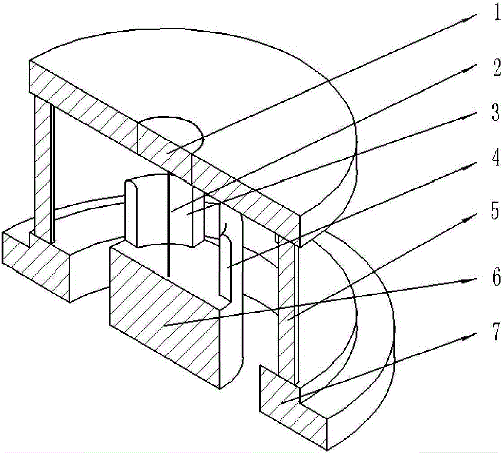
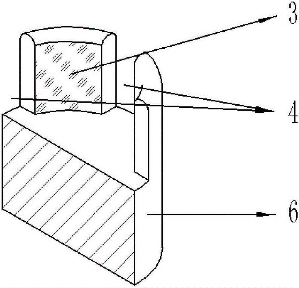
[0020] figure 1 Shown is a schematic diagram of a Z-pinch load structure with a positive radial electric field, including a load anode 1, a metal wire 2, a return column 5, a load cathode 6, and a device anode 7, and the load anode 1 and the load cathode 6 are arranged coaxially opposite each other. The diameter of the load anode is larger than the diameter of the load cathode; one end of the metal wire is connected to the load anode, and the other end of the wire is connected to the load cathode; the return column is located outside the load cathode, and the load anode is connected to the anode of the device through the return column. The load anode, equipment anode, return column and other structures are the same as the traditional load. The difference between the loading structure of the present invention and the traditional loading structure lies in the differen...


PUM


Abstract

The invention relates to a Z-pinching load structure with a positive polarity radial electric field. The Z-pinching load structure has a different load negative electrode structure from the traditional load structure. The Z-pinching load structure is improved on the basis of the conventional load negative electrode with the cylindrical structure; the load negative electrode structure is changed into a column-barrel-shaped structure which extends towards a positive electrode; after the load negative electrode is changed into the column-barrel-shaped structure, the radial electric field on the surface of metal wires is mainly affected by the load negative electrode; and the load negative electrode is lower in potential, so that the direction of the radial electric field is changed into the direction from the surface of the metal wires to the load negative electrode so as to restrain the electron emission on the surface of the metal wires in the early period, slow down the formation of corona plasma, prolong the ohmic heating time of the current in the interior of the metal wires, and weaken the adverse influences on the implosion process and even the X-ray radiation from the nuclear-coronal structure.

Description

technical field [0001] The invention belongs to experimental devices, in particular to a Z pinch load structure. Background technique [0002] In Z-pinch experiments, pulsed power sources are usually discharged with negative polarity. In the traditional load structure (G.S.Sarkisov, S.E.Rosenthal, K.W.Struve, T.E.Cowan, R.Presura, A.L.Astanovitskiy, A.Haboub, and A.Morozov.Physics of Plasmas.14,112701.(2007)), the load cathode and The geometry of the loaded anode can be simplified as two metal cylinders placed opposite each other, and the wire array is located between the two cylinders. During pulse discharge, electrons flow back to the load anode along the load cathode through the metal wire, and finally reach the anode of the pulse power device through the return column. Under the constraint of the above geometric structure, in the early stage of current rise, the surface of the metal wire must be affected by the negative polarity radial electric field, which will cause ...

Claims


Application Information

Patent Timeline
IPC IPC(8): H05H1/04
CPCH05H1/04
Inventor 李沫张金海李阳王亮平盛亮孙铁平毛文婷
Owner NORTHWEST INST OF NUCLEAR TECH
Why Eureka
Try Eureka