
Quasi-phase matching and quantum control of high harmonic generation in waveguides using counterpropagating beams

a quantum control and waveguide technology, applied in the direction of laser using scattering effects, electrical apparatus, laser details, etc., can solve the problems of significant modulation in both amplitude and phase of harmonics, inability to use hhg, and difficulty in optimizing the modulation period, so as to enhance high-harmonic emission

Inactive Publication Date: 2008-06-12
UNIV OF COLORADO THE REGENTS OF
View PDF2 Cites 22 Cited by
  • Summary
  • Abstract
  • Description
  • Claims
  • Application Information

AI Technical Summary

Benefits of technology

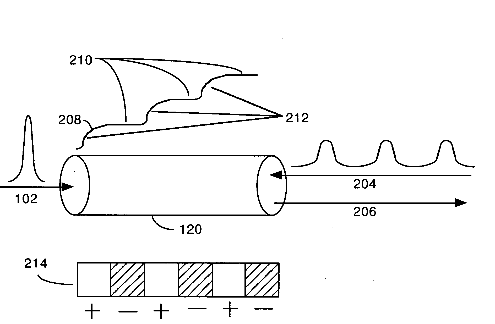
[0015]An object of the present invention is to use a train of counterpropagating light pulses to enhance high-harmonic emission in a waveguide. This all-optical quasi-phase-matching technique uses interfering beams to scramble the quantum phase of the generated short-wavelength light, to suppress emission from out-of-phase regions.

Problems solved by technology

The major challenge is that, unlike low-order nonlinear processes such as second-harmonic generation, HHG is inherently associated with ionization of the nonlinear medium.
Thus, new methods that can correct for this phase mismatch in ionized media (plasmas) are a ‘grand challenge’ in this area of laser science.
However, this implementation cannot be used for HHG, because HHG uses a low-pressure gas as the nonlinear medium.
Even a small modulation (around 1%) of the driving laser results in significant modulation in both the amplitude and phase of the harmonics.
This is because optical loss of the driving laser, refraction, mode beating and group-velocity dispersion all result in a continuous variation of the coherence length along the direction of propagation, making it difficult to optimize the modulation period.
Finally, modulation periods shorter than the waveguide diameter will not significantly influence the laser field, making it challenging to compensate for very short coherence lengths.
However, this work only investigated harmonic emission in regimes where conventional phase-matching was already possible in the medium.
Attempts to obtain enhancements significantly greater than what could otherwise be obtained were not successful.

Method used


Image

  • Quasi-phase matching and quantum control of high harmonic generation in waveguides using counterpropagating beams
  • Quasi-phase matching and quantum control of high harmonic generation in waveguides using counterpropagating beams
  • Quasi-phase matching and quantum control of high harmonic generation in waveguides using counterpropagating beams

Examples


Embodiment Construction

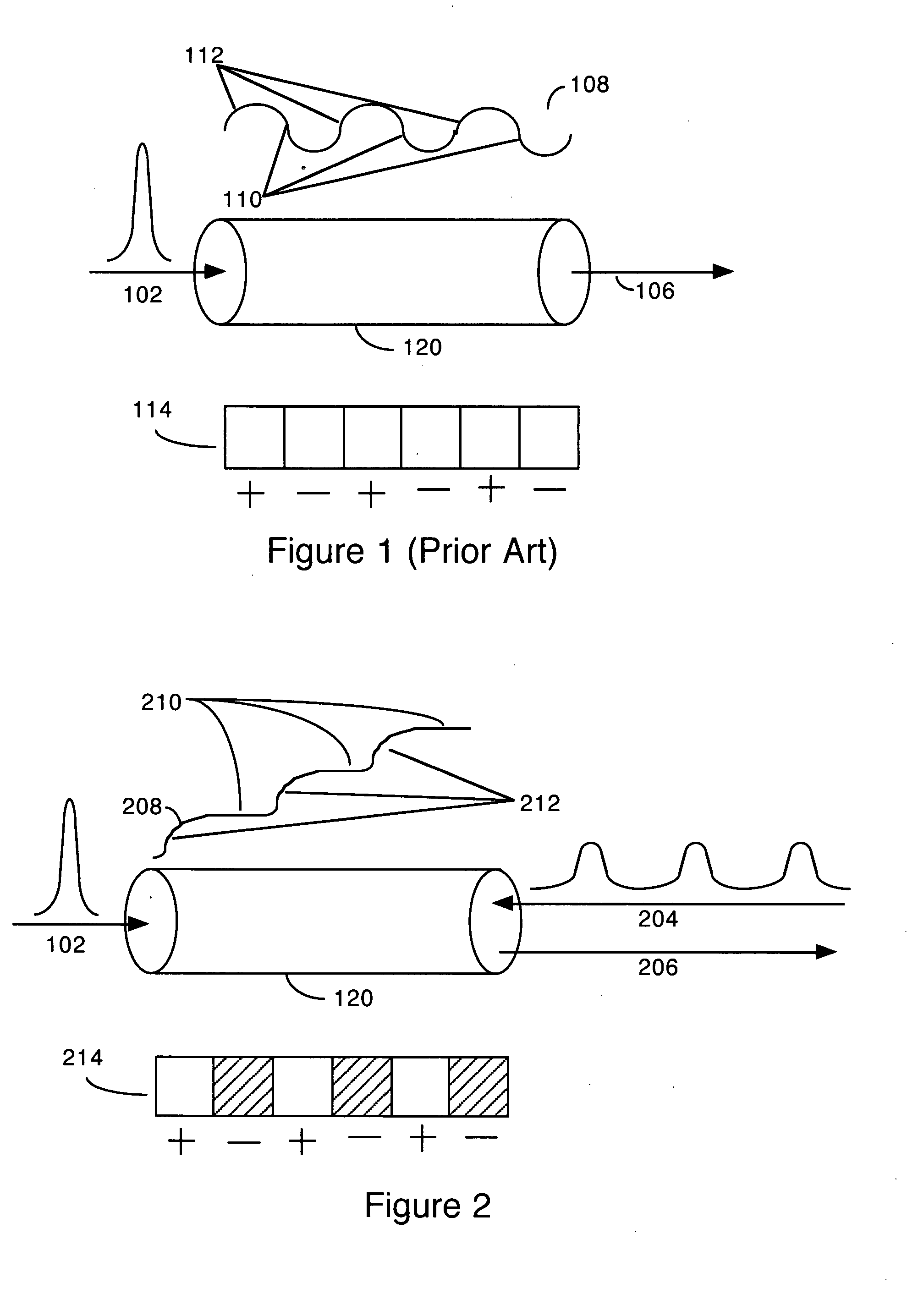
[0026]FIG. 1 (Prior Art) is a schematic diagram illustrating high-harmonic emission generation (HHG) in a waveguide where the process is not phase-matched, and without quasi-phase matching. Input pulse 103 comprises a femtosecond laser pulse, which enters hollow waveguide 120. Signal waveform 108 gives a general indication of the amplitude of HHG over the path length of pulse 102 through waveguide 120. Diagram 114 indicates the regions within waveguide 120 in which constructive and destructive interference of HHG emissions will occur, due to the short coherence length of the HHG beam. The areas indicated by a plus (+) are areas of constructive interference, while the areas indicated by a minus (−) are areas of destructive interference. The length of the plus and minus areas is exactly one coherence length.

[0027]Hence, at first the HHG amplitude increases, but as the coherence length is reached destructive interference causes the amplitude to decrease. This process is repeated with a...


PUM


Abstract

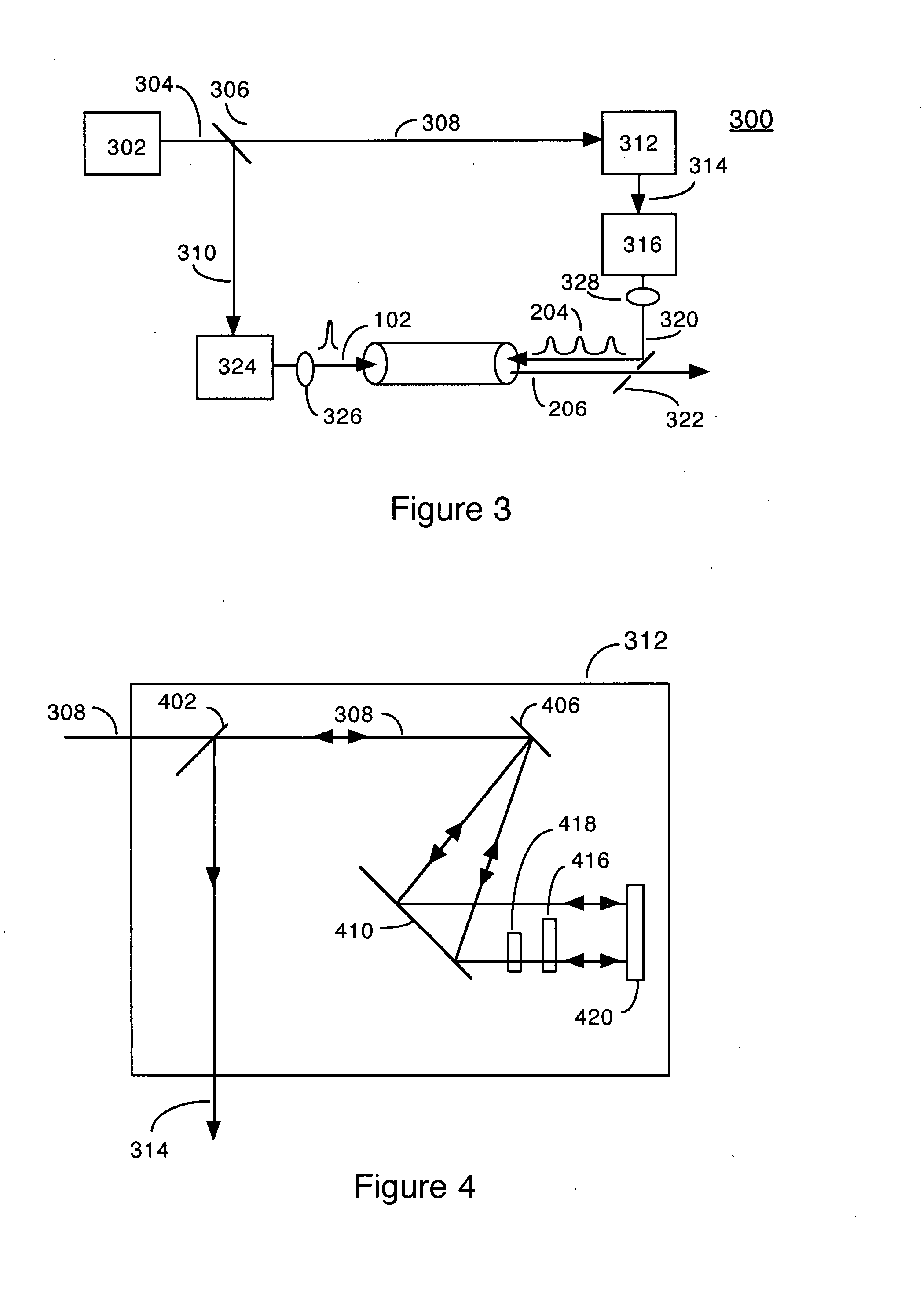
All-optical quasi-phase matching (QPM) uses a train of counterpropagating pulses to enhance high-order harmonic generation (HHG) in a hollow waveguide. A pump pulse enters one end of the waveguide, and causes HHG in the waveguide. The counterpropagation pulses enter the other end of the waveguide and interact with the pump pulses to cause QPM within the waveguide, enhancing the HHG.

Description

PRIORITY[0001]This application claims benefit of U.S. Provisional Patent Application No. 60 / 835,138, filed Aug. 2, 2006 and incorporates it therein by reference.GOVERNMENT SUPPORT [0002]The present invention was made with government support as follows, and the U.S. Government has certain rights in the invention.[0003]National Science Foundation Cooperative Agreement No. EEC-0310717, “NSF Engineering Research Center in Extreme Ultraviolet Science and Technology.”[0004]Department of Energy, National Nuclear Security Administration, Grant No. DE-FG52-06NA26151, “Investigations of Laser Materials Interactions using Ultrafast Short-Wavelength Light.”BACKGROUND OF THE INVENTION[0005]1. Field of the Invention[0006]The present invention relates to high harmonic generation (HHG) using quasi-phase matching (QPM) via counterpropagating pulse trains in waveguides.[0007]2. Description of the Prior Art[0008]High-order harmonic generation (HHG) driven by ultrashort laser pulses is a source of extr...

Claims


Application Information

Patent Timeline
Patent Type & Authority Applications(United States)
IPC IPC(8): H01S3/10
CPCH01S4/00H05G2/008H05G2/003
Inventor ZHANG, XIAOSHILYTLE, AMY L.COHEN, ORENKAPTEYN, HENRY C.MURNANE, MARGARET M.
Owner UNIV OF COLORADO THE REGENTS OF
Learn More