
Bistatic MIMO radar signal processing method based on distance-orientation coupling

A radar signal processing and bistatic technology, applied in the field of radar detection, can solve problems such as large amount of computation, distance delay of target echo signal, difficult to meet actual needs, etc., to achieve the effect of reducing the amount of computation

Active Publication Date: 2016-09-28
XIDIAN UNIV
View PDF6 Cites 7 Cited by
  • Summary
  • Abstract
  • Description
  • Claims
  • Application Information

AI Technical Summary

Problems solved by technology

In order to perform signal processing effectively, the traditional bistatic MIMO radar signal processing method first performs receiving beamforming on the array echo signal, then performs time-domain matching filtering on the received beamforming to separate the transmitting signal, and finally performs Transmit beamforming; among them, the time-domain matched filtering of M channels is required for each formation of a transmit beam, and M is the number of transmitting array elements of the bistatic MIMO radar, which leads to a large amount of computation for bistatic MIMO radar signal processing, which is difficult meet actual needs
[0003] Orthogonal frequency division multiplexing linear frequency modulation (OFD-LFM) signals are widely used in MIMO radar; Duan Xiang et al. March", pointed out that when the bistatic MIMO radar transmits OFD-LFM signals, the azimuth and distance in the target echo signal are coupled, that is, the target echo signal has a range-azimuth coupling phenomenon; the range-azimuth coupling phenomenon indicates that the target The difference in the launch angle, or the delay in the distance in the target echo signal

Method used


Image

  • Bistatic MIMO radar signal processing method based on distance-orientation coupling
  • Bistatic MIMO radar signal processing method based on distance-orientation coupling
  • Bistatic MIMO radar signal processing method based on distance-orientation coupling

Examples


Embodiment Construction

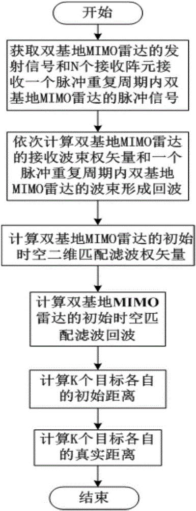
[0021] refer to figure 1 , is a flow chart of a bistatic MIMO radar signal processing method based on range-azimuth coupling of the present invention; the bistatic MIMO radar signal processing method based on range-zimuth coupling comprises the following steps:

[0022] Step 1. Determine that the bistatic MIMO radar includes M transmitting array elements and N receiving array elements, and obtain the transmitting signal S of the bistatic MIMO radar. The transmitting signal S of the bistatic MIMO radar is an OFD-LFM signal, where the first The transmitting signal of m transmitting array elements is s m ; The pulse echo of bistatic MIMO radar received by N receiving array elements within a pulse repetition period is X,

[0023] X=[x 1 ,...,x n ,...,x N ] T , x n Receive the pulse echo of the bistatic MIMO radar within a pulse repetition period for the nth receiving element, x n =[x n1 ,...,x nl ,...,x nL ] T , x nl is the pulse echo of the bistatic MIMO radar at the ...


PUM


Abstract

The invention discloses a bistatic MIMO radar signal processing method based on distance-orientation coupling. The method mainly comprises steps that bistatic MIMO radar emission signals are respectively acquired, and bistatic MIMO radar pulse echoes within a pulse repetition period are received by N reception array elements; wavelength of the bistatic MIMO radar emission signals, array element intervals of the N MIMO radar reception array elements and bistatic MIMO radar reception wave beam directions are respectively determined; bistatic MIMO radar wave beam formation echoes with a pulse repetition period are calculated; a bistatic MIMO radar initial emission angle is set, and a bistatic MIMO radar initial space-time matching filtering echo z is calculated; a bistatic MIMO radar sampling time interval is set, target detection on the z is carried out, correction is carried out after respective initial distances of K targets are acquired, and thereby respective true distances of the K targets are acquired.

Description

technical field [0001] The invention belongs to the technical field of radar detection, and specifically relates to a bistatic MIMO radar signal processing method, which can be used to reduce the calculation amount of bistatic MIMO radar signal processing. Background technique [0002] Bistatic MIMO radar has the advantages of anti-stealth, anti-jamming and anti-radiation missiles. However, the receiving station and the transmitting station of the bistatic radar are far away from each other, and the perspective of the target relative to the transmitting station and the receiving station is different. In order to perform signal processing effectively, the traditional bistatic MIMO radar signal processing method first performs receiving beamforming on the array echo signal, then performs time-domain matching filtering on the received beamforming to separate the transmitting signal, and finally performs Transmit beamforming; among them, the time-domain matched filtering of M ch...

Claims


Application Information

Patent Timeline
IPC IPC(8): G01S7/41
CPCG01S7/41
Inventor 赵永波程增飞李慧刘宏伟苏洪涛张盼盼
Owner XIDIAN UNIV
Learn More