
A mechanical shock absorber

A technology of mechanical shock absorption and hydraulic shock absorption, which is applied in the direction of shock absorbers, mechanical equipment, springs/shock absorbers, etc., can solve the problems of poor shock absorption effect, inconvenient installation, large amount of wear, etc., and achieve safe use Performance, easy installation and disassembly, good shock absorption effect

Active Publication Date: 2018-09-28
YANGZHOU STRVALUE INFORMATION TECH CO LTD
View PDF6 Cites 0 Cited by
  • Summary
  • Abstract
  • Description
  • Claims
  • Application Information

AI Technical Summary

Problems solved by technology

The shock absorbers and damping devices in the prior art generally convert the mechanical energy of the vibration of the equipment into the mechanical energy of the oil, and then into the internal energy of the oil, and finally discharge the heat to eliminate the shock, so it is necessary to have enough The space is mechanically moved to ensure sufficient movement of the oil; when the piston of the shock absorber is compressed, the oil flows from the breathing chamber to the working chamber and the oil storage chamber; when the shock absorber is stretched, the oil flows from the working chamber to the oil storage chamber Breathing chamber, but the structural design of such shock absorbers and shock absorbing equipment in the prior art is complicated, installation is inconvenient, and fuel consumption is large, and the economic cost of production and application is relatively high
[0003] At present, the shock absorbers and shock absorbers in the prior art and the shock absorbers and shock absorbers in the traditional technology have basically adopted shock absorbing damping springs. The bigger the shock absorber and shock absorber in the traditional technology, the damping spring and the pulley (including the slide rail) cooperate to achieve a certain degree of shock absorption effect, and there is almost no energy loss. However, the shock absorption effect In addition, the parts of the shock absorber have a lot of wear and tear during long-term work, and they need to be replaced frequently, which brings inconvenience to the use

Method used


Image

  • A mechanical shock absorber
  • A mechanical shock absorber
  • A mechanical shock absorber

Examples


Embodiment Construction

[0020] The content of the present invention will be described below in conjunction with specific embodiments.

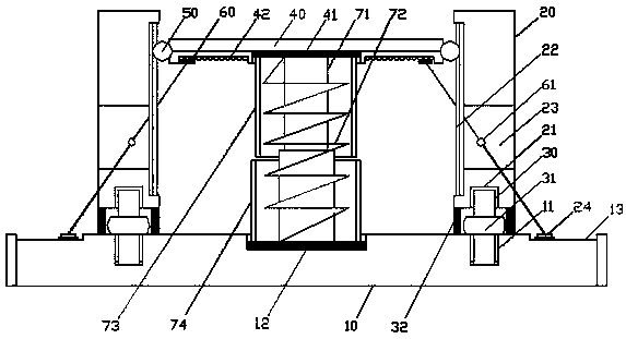
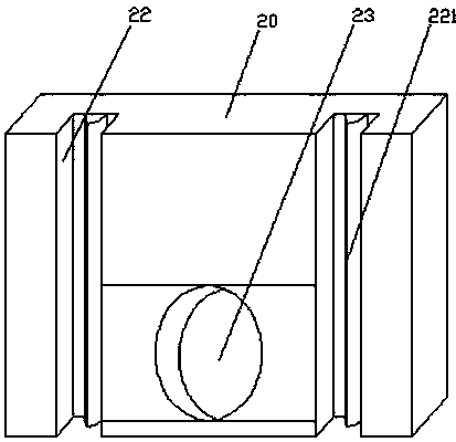
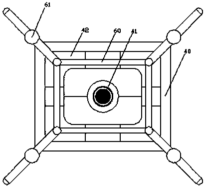
[0021] Such as Figure 1 to Figure 5 Shown is a structural schematic diagram of a mechanical damping device according to the present invention.

[0022] A mechanical damping device according to the present invention comprises a base 10 and two sets of damping baffles 20, the two sets of damping baffles 20 are arranged in parallel on both sides of the end face of the base 10, and several groups of No. 1 fixing screws are processed on both sides of the end face of the base 10. Holes 11 and the bottom of the damping partition 20 are all processed with a number of No. 2 fixing screw holes 21 used in conjunction with the No. 1 fixing screw hole 11, and the No. 1 fixing screw hole 11 and the No. 2 fixing screw hole 21 are provided with a connection base 10 and a damping partition. The connecting threaded rod 30 of the plate 20 is provided with an adjusting nut 31 for adju...


PUM


Abstract

The invention discloses a mechanical vibration reducing device. The mechanical vibration reducing device comprises a base and two sets of damping separation plates; fixed screw holes 1 are formed in the base; fixed screw holes 2 are formed in the damping separation plates; connecting thread rods are arranged in the fixed screw holes 1 and the fixed screw holes 2, and are provided with adjusting nuts; elastic vibration reducing damping columns are arranged between the base and the damping separation plates; chutes are formed in two inner side walls of the damping separation plates; vibration reducing brackets are arranged between two chutes; connecting grooves 1 are formed in the vibration reducing brackets; connecting grooves 2 are formed in the base; and hydraulic vibration reducing damping mechanisms are arranged between the connecting grooves 1 and the connecting grooves 2. The mechanical vibration reducing device is excellent in vibration reducing effect, can reduce the oil consumption to the greatest extent, can reduce the wear of parts of the vibration reducing device to the greatest extent, is stable in performance in the vibration reducing process, is convenient for installation and disassembly, saves both time and labors, greatly improves the mechanical vibration reduction working efficiency, is better in safe use performance, and satisfies actual use requirements.

Description

technical field [0001] The invention specifically relates to a mechanical shock absorber, which belongs to the technical field of mechanical shock absorbers and shock absorbers. Background technique [0002] With the improvement of the quality of life, people's requirements for the comfort of the vehicle are also increasing. In order to increase the comfort of the vehicle, the automobile chassis system uses shock absorbers for shock absorption and buffering. The shock absorber used in the automobile suspension system Most of them are hydraulic shock absorbers. Its working principle is that when the car is bumped, the piston in the shock absorber moves up and down, and repeatedly beats the oil in the cylinder of the shock absorber to convert the vibration energy of the car into oil. The heat energy of the liquid is absorbed by the shock absorber and released into the atmosphere. The installation of shock absorbers and shock absorbing devices can adjust the level of equipment...

Claims


Application Information

Patent Timeline
Patent Type & Authority Patents(China)
IPC IPC(8): F16F13/00
CPCF16F13/007
Inventor 国际昌
Owner YANGZHOU STRVALUE INFORMATION TECH CO LTD
Learn More