
Four-rail blade lock

A blade lock and blade technology, applied in construction locks, cylinder pin locks, locks with turning keys, etc., can solve the problems of low safety factor and easy to be moved, and achieve technical unlocking prevention, good anti-theft performance, and improved The effect of the factor of safety

Active Publication Date: 2016-09-28
陈文宁
View PDF6 Cites 1 Cited by
  • Summary
  • Abstract
  • Description
  • Claims
  • Application Information

AI Technical Summary

Problems solved by technology

[0002] At present, there are 3 to 7 blade holes in the lock cylinder of the existing blade lock, and each blade hole is equipped with two blades, and the blades are provided with V-shaped gaps. The gaps are aligned in a straight line, the edge of the side column falls into the V-shaped gap of the blade, the outer edge of the side column and the outer circle of the lock cylinder are on the same arc surface, the lock cylinder can be rotated, when the key is pulled out or inserted incorrectly When the key is used, the V-shaped notch on the blade is not in a straight line, the outer edge of the side column is higher than the outer arc surface of the lock cylinder, the lock cylinder cannot be rotated, and the lock cylinder is in a locked state, but when the teeth of the two keys are closer It is possible to open each other, and the two blades in the blade holes are easy to be moved, and the two blades can be easily moved to the open position through the unlocking technology, and the safety factor is low.

Method used


Image

  • Four-rail blade lock
  • Four-rail blade lock
  • Four-rail blade lock

Examples


Embodiment Construction

[0025] The present invention will be further explained below in conjunction with specific embodiments. It should be understood that these embodiments are only used to illustrate the present invention and not to limit the scope of the present invention. In addition, it should be understood that after reading the teachings of the present invention, those skilled in the art can make various changes or modifications to the present invention, and these equivalent forms also fall within the scope defined by this application.

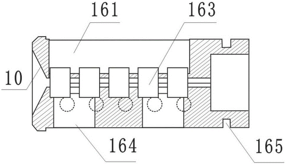
[0026] The present invention is a four-track blade lock, which includes a lock core and a key 17, and the lock core includes a lock body 1. The lock body 1 is provided with a lock cylinder 16, and the lock body 1 is provided with a mounting hole 6. A dial 7 is provided below the mounting hole 6, a clamp ring 13 is provided at both ends of the dial 7, a slider 12 is provided in the dial 7, and a push post 11 is provided at one end of the slider 12, The push colu...


PUM


Abstract

The invention discloses a four-rail blade lock, and mainly relates to the field of safety lock technical equipment. The four-rail blade lock comprises a lock cylinder and a key, the lock cylinder comprises a lock body, a lock liner is arranged in the lock body, multiple blade holes are formed in the lock liner, four blades are arranged in each blade hole, springs are arranged under the blades, disturbance side column containing grooves are formed below the blade holes, disturbance side columns are arranged in the disturbance side column containing grooves, a locking side column containing groove is formed in the tops of the blade holes, and a locking side column is arranged in the locking side column containing groove; three groups of front face teeth are arranged on the front face of the key, and a group of back face teeth are arranged on the back face of the key. The four-rail blade lock has the advantages that four blades are installed in each blade hole, it can be avoided that the blades are poked into the unlocking position through an unlocking technology, and safety coefficient can be increased; the teeth on the key can be combined in many modes, the lock is prevented from being unlocked by a similar key, and the anti-theft performance is good.

Description

Technical field [0001] The invention relates to the field of safety lock technical equipment, in particular to a four-track blade lock. Background technique [0002] At present, there are 3-7 blade holes in the cylinder of the existing blade lock. Each blade hole is equipped with two blades. The blades are provided with V-shaped notches. When the correct key is inserted, the V-shaped The notches are aligned in a straight line, the edge of the side post falls into the V-shaped notch of the blade, and the outer edge of the side post and the outer circle of the lock cylinder are on the same arc surface. The lock cylinder can be rotated. When the key is removed or the wrong one is inserted When keying, the V-shaped notch on the blade is not in a straight line, the outer edge of the side column is higher than the outer arc surface of the cylinder, the cylinder cannot be rotated, and the lock cylinder is in the locked state, but when the teeth of the two keys are closer At this time, ...

Claims


Application Information

Patent Timeline
IPC IPC(8): E05B27/08E05B19/00
CPCE05B19/00E05B27/0017E05B27/08
Inventor 陈文宁
Owner 陈文宁
Learn More