
A construction method for main girder side-span closure for composite girder cable-stayed bridges

A construction method and side-span technology, applied in bridges, bridge construction, erection/assembly of bridges, etc., can solve the problems of three-way consolidation system design and construction difficulties, concrete construction quality is difficult to guarantee, and construction technology is complicated, etc., to achieve reduction Minimize the interference of external environmental factors, ensure the construction quality, and ensure the effect of accurate docking

Active Publication Date: 2017-11-10
CCCC SECOND HARBOR ENG
View PDF5 Cites 0 Cited by
  • Summary
  • Abstract
  • Description
  • Claims
  • Application Information

AI Technical Summary

Problems solved by technology

For the first method, three-way temporary consolidation must be installed in the cable tower area of ​​the combined beam main beam in the cantilever construction. If the three-way temporary consolidation is set at the end section of the side span, the entire side span main beam is in a rigid restraint state , under the influence of changes in the construction environment and various loads, the main girder is prone to produce secondary stresses that lead to quality problems such as deformation and cracking, and the design and construction of the three-dimensional consolidation system are relatively difficult; for the second method, although it is not necessary Temporary consolidation measures, but the construction process is complex, affected by the closed space, the quality of concrete construction is difficult to guarantee, especially the shrinkage and creep of concrete can easily cause the concrete to be separated from the steel box, forming hollows

Method used


Image

  • A construction method for main girder side-span closure for composite girder cable-stayed bridges
  • A construction method for main girder side-span closure for composite girder cable-stayed bridges
  • A construction method for main girder side-span closure for composite girder cable-stayed bridges

Examples


Embodiment Construction

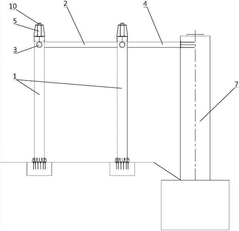
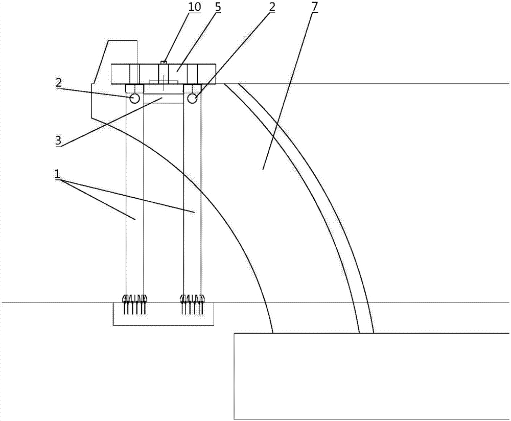
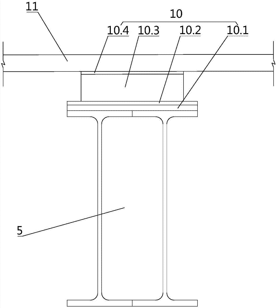
[0032] pass below Figure 1 to Figure 8 And the way of enumerating some optional embodiments of the present invention, the technical solution of the present invention (including the preferred technical solution) is described in further detail, and any technical feature and any technical solution in this embodiment do not limit the protection scope of the present invention .

[0033] The main girder side-span closure construction method for the combined girder cable-stayed bridge designed by the present invention comprises the following steps:

[0034] 1) Set up a support slideway system in the area of ​​the end beam section. The support slideway system includes a steel pipe support device and a slideway device:

[0035] ①Establish the steel pipe support device, the steel pipe support device includes steel pipe column 1, the first parallel joint 2, the second parallel joint 3 and the third parallel joint 4, such as figure 1 and figure 2 As shown: a plurality of vertically a...


PUM


Abstract

The invention discloses a main beam side-span closure construction method for a bond beam cable-stayed bridge. Suspension splicing installation is not conducted on a side-span tail end beam section. A tail-section steel beam is spliced and constructed through a landing steel pipe support. End cross beam reinforced concrete is constructed through a scaffold. A side-span closure opening is additionally formed between the side-span tail end beam section and a sub-tail end beam section. Through reverse pre-deviation of an end cross beam (including a support top board) and jacking reset of the end cross beam, the problem about matching of a bond beam and a standard bond beam section after the end cross beam is poured is effectively solved.

Description

technical field [0001] The invention relates to the field of bridge construction, in particular to a main girder side span closing construction method for a combined girder cable-stayed bridge. Background technique [0002] For the design of steel-concrete combined beams, reinforced concrete end beams are generally used as counterweights at the end beam sections of the side spans. The end beams are cast-in-place and integrated with the steel beams, and connected to the piers through vertical supports. [0003] Due to the long construction period of the end beam and the large cantilever state of the combined beam, due to the influence of temperature, wind vibration and other factors, the combined beam is in an unstable state, and the quality of concrete pouring is difficult to control. In order to ensure the construction period and construction quality, there are generally two traditional construction methods: one is to fix the end steel beam in three directions by setting te...

Claims


Application Information

Patent Timeline
Patent Type & Authority Patents(China)
IPC IPC(8): E01D21/06
CPCE01D21/06
Inventor 黄成伟胡义新代岳龙黄灿周益军
Owner CCCC SECOND HARBOR ENG
Learn More