
A workpiece clamping device for a CNC brake camshaft grinder

A camshaft and workpiece clamp technology, which is applied in the direction of grinding workpiece supports, grinders, abrasive belt grinders, etc., can solve the problems of inconvenient use and inflexibility of camshaft clamps, and achieve the effect of solving inflexibility

Active Publication Date: 2019-03-26
QUANZHOU LICHENG FUHUI AUTOMOBILE PARTS CO LTD
View PDF5 Cites 0 Cited by
  • Summary
  • Abstract
  • Description
  • Claims
  • Application Information

AI Technical Summary

Problems solved by technology

The camshaft is usually ground by a CNC camshaft grinder. During grinding, the camshaft is clamped in the top and tail tips, and the top drives the workpiece to rotate. The feed movement of the grinding wheel is linked with the rotation of the workpiece to process the For camshafts that meet the requirements, the existing camshaft fixtures are very inflexible, and most of them are limited by manual operation, which is very inconvenient to use. For this reason, we propose a workpiece clamping device for a CNC brake camshaft grinder to solve the problem. above question

Method used


Image

  • A workpiece clamping device for a CNC brake camshaft grinder
  • A workpiece clamping device for a CNC brake camshaft grinder
  • A workpiece clamping device for a CNC brake camshaft grinder

Examples


Embodiment Construction

[0014] The following will clearly and completely describe the technical solutions in the embodiments of the present invention with reference to the accompanying drawings in the embodiments of the present invention. Obviously, the described embodiments are only some, not all, embodiments of the present invention. Based on the embodiments of the present invention, all other embodiments obtained by persons of ordinary skill in the art without making creative efforts belong to the protection scope of the present invention.

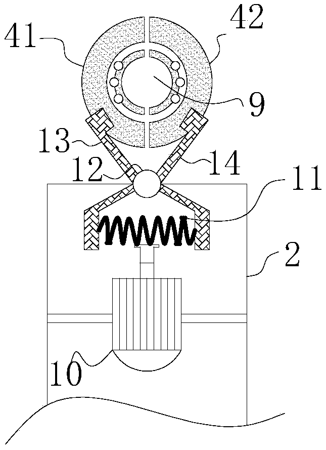
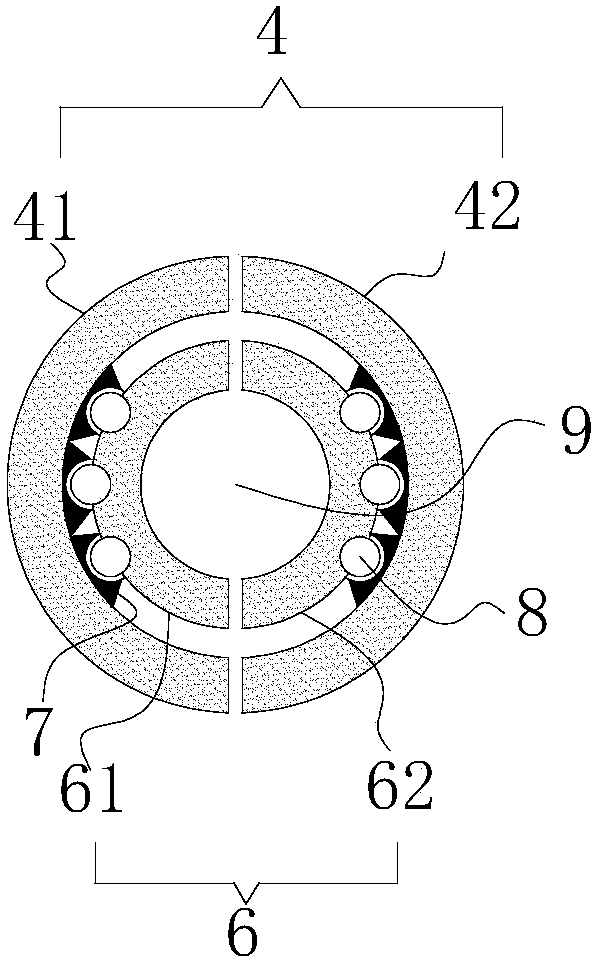
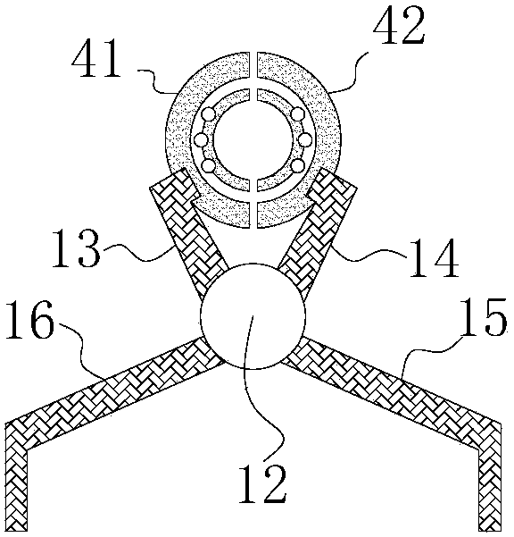
[0015] see Figure 1-4 , the present invention provides a technical solution: a workpiece clamping device for a CNC brake camshaft grinder, comprising a grinder base 1, the left and right ends of the upper surface of the grinder base 1 are respectively fixedly installed with a second clamp support rod 3 and a first clamp support The rod 2, the first clamp support rod 2 and the second clamp support rod 3 are respectively provided with a clamp head 4, and a work...


PUM


Abstract

The invention discloses a work-piece clamping device of a numerically-controlled brake camshaft grinding machine. The work-piece clamping device comprises a grinding machine base, a second clamp supporting rod and a first clamp supporting rod are fixedly installed at the left end and the right end of the upper surface of the grinding machine base, clamp heads are arranged on the first clamp supporting rod and the second clamp supporting rod, a work-piece to be machined is movably clamped between the two clamp heads, and electric telescopic rods are fixedly installed inside a cavity of the first clamp supporting rod and a cavity of the second clamp supporting rod. According to the structure of the work-piece clamping device, tension springs are elastically stretched through telescoping regulation of the electric telescopic rods, mutual rotation of first clamping blocks and second clamping blocks is realized through clamping blocks movably arranged on fixing pin shafts in a sleeving mode and limiting rods, and therefore the clamp heads can be controlled to clamp or loosen the work-piece to be machined, rotary machining of an externally-connected motor can be easily realized through cooperation among ball limiting bases, balls and a bearing lantern ring, and the problem that the clamp heads are not flexible is well solved.

Description

technical field [0001] The invention relates to the technical field of grinding machine-related equipment, in particular to a workpiece clamping device for a numerically controlled brake camshaft grinder. Background technique [0002] Camshafts are widely used in gasoline engines or diesel engines to control the switching of fuel injection pumps or the opening and closing of intake and exhaust valves. The quality of the camshaft directly determines the performance of the engine. The camshaft is usually ground by a CNC camshaft grinder. During grinding, the camshaft is clamped in the top and tail tips, and the top drives the workpiece to rotate. The feed movement of the grinding wheel is linked with the rotation of the workpiece to process the For camshafts that meet the requirements, the existing camshaft fixtures are very inflexible, and most of them are limited by manual operation, which is very inconvenient to use. For this reason, we propose a workpiece clamping device f...

Claims


Application Information

Patent Timeline
Patent Type & Authority Patents(China)
IPC IPC(8): B24B41/06B24B19/12
CPCB24B19/125B24B41/062
Inventor 吴永成许英英吴萍莉吴萍瑜吴艳艳
Owner QUANZHOU LICHENG FUHUI AUTOMOBILE PARTS CO LTD
Learn More