
Workbench for cleaning and recycling waste scraps generated in machine element processing

A technology of mechanical parts and workbenches, which is applied in the field of parts processing, can solve problems such as splashing in the air, high processing precision of workpieces, and physical hazards, and achieve the effects of ensuring personal safety, ingenious structural design, and thorough cleaning

Inactive Publication Date: 2016-09-28
江苏力栋机械科技有限公司
View PDF5 Cites 28 Cited by
  • Summary
  • Abstract
  • Description
  • Claims
  • Application Information

AI Technical Summary

Problems solved by technology

However, this type of waste usually also has many burrs, and most of them are sharp and irregular shapes. When they are allowed to accumulate on the workbench or the ground, it is easy to cause abrasions or cuts to the exposed skin of the operator. The accumulated waste is also likely to affect the subsequent processing work, and some workpieces require high processing precision, and the generated debris is relatively small. If you wipe it directly with a tablecloth, it is easy to splash in the air for a short time and become metal "dust". The air of metal "dust" is extremely harmful to the body

Method used


Image

  • Workbench for cleaning and recycling waste scraps generated in machine element processing
  • Workbench for cleaning and recycling waste scraps generated in machine element processing
  • Workbench for cleaning and recycling waste scraps generated in machine element processing

Examples


Embodiment Construction

[0016] The technical solution of this patent will be further described in detail below in conjunction with specific embodiments.

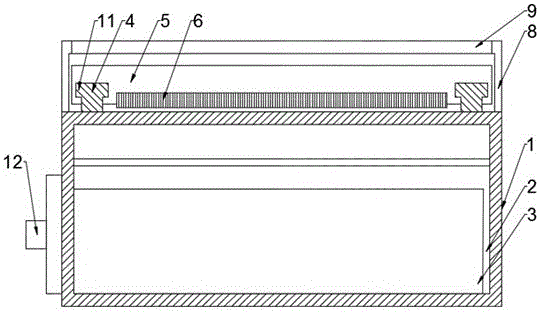
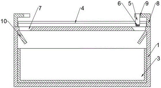
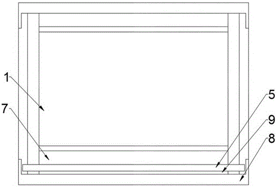
[0017] see Figure 1~3 , a workbench for cleaning and recycling mechanical parts processing waste, including a table body 1, a chip removal chamber 2 is provided in the table body 1, a drawer 3 is provided in the discharge chamber, and the left and right ends of the table surface of the table body 1 are Two guide rails 4 are arranged symmetrically. The guide rails 4 are designed with a T-shaped structure. A scraper 5 is provided directly above the table body 1. The bottom end of the scraper 5 is embedded with a brush 6. Both ends of the scraper 5 The bottom surface is symmetrically provided with a guide groove 11 matched with the guide rail 4. The guide groove 11 is also a T-shaped structure design. The front and rear ends of the table body 1 are symmetrically provided with two baffles 8. Baffle plate and horizontal baffle plate, the cross-section...


PUM


Abstract

The invention discloses a workbench for cleaning and recycling waste scraps generated in machine element processing. The workbench comprises a workbench body. A scrap removal cavity is formed in the workbench body; a drawer is arranged in the scrap removal cavity; two guide rails are symmetrically arranged on the left end and the right end of a table top of the workbench body; a scraper blade is arranged right above the workbench body; hairbrushes are embedded into the bottom end of the scraper blade; guide slots matched with the guide rails are symmetrically formed on the bottom face of two ends of the scraper blade; two baffle plates are symmetrically arranged on the front end and the rear end of the workbench body and comprise vertical baffle plates and horizontal baffle plates; the cross section of the vertical baffle plates is of a concave structure; grooves are formed at opposite ends of the two horizontal baffle plates; the length of each groove is larger than the length of the scraper blade; the workbench body is provided with scrap removal holes near the baffle plates; guide plates for the scrap removal holes are arranged on the top end of the side wall of the scrap removal cavity, and are slantways arranged. The workbench for cleaning and recycling the waste scraps generated in machine element processing provided by the invention is ingenious in structural design, element waste scraps on the table top of the workbench body are swept to and fro so as to be cleanly and thoroughly swept, and the waste scraps are directly fallen into a scrap removal chamber, so that the personal safety of the cleaning crews is ensured.

Description

technical field [0001] The invention relates to the field of parts processing, in particular to a workbench for cleaning and recycling mechanical parts processing waste. Background technique [0002] The basic elements that make up machinery are called mechanical parts. Machine elements, also known as mechanical elements, are inseparable individual parts that make up machinery and machines. It is the basic unit of machinery. [0003] In the existing machining factories or machining workshops, a large amount of waste will be generated during the processing of mechanical parts. One of the general treatment methods is to let them scatter around, and the other is to use tablecloths or other tools to remove them. It is wiped on the ground, and then cleaned and recovered after a period of time. However, this type of waste usually also has many burrs, and most of them are sharp and irregular shapes. When they are allowed to accumulate on the workbench or the ground, it is easy to ...

Claims


Application Information

Patent Timeline
IPC IPC(8): B23Q11/00
CPCB23Q11/0042
Inventor 颜声林
Owner 江苏力栋机械科技有限公司
Learn More