Quick-lock anti-auxetic tire for inner hole and end face positioning workpiece

A technology for end faces and workpieces, which is applied in the field of high-precision fast locking fixtures, can solve problems such as efficiency impact, low precision, and influence on end face processing, and achieve the effects of improving processing efficiency, large operating space, and fast locking

Active Publication Date: 2018-10-19
BEIJING INST OF AEROSPACE CONTROL DEVICES
View PDF6 Cites 0 Cited by
  • Summary
  • Abstract
  • Description
  • Claims
  • Application Information

AI Technical Summary

Problems solved by technology

The positioning of the inner hole often uses tire expansion. Generally, the outer wall of the cone mandrel of the tire is provided with threads, which are screwed in the direction of the end face of the part. In order to achieve the reliability of the tire expansion, the thread of the cone mandrel is very long and needs to be rotated many times. In order to realize the clamping or dismounting of the workpiece, the efficiency is low
Moreover, it affects the processing of the end face, and is not suitable for the needs of fast clamping and positioning of CNC machine tools
[0004] Processing by the above method, the average clamping time is longer, because the end face cannot be formed at one time, the precision is low, and the secondary positioning processing has a serious impact on the efficiency

Method used


Image

  • Quick-lock anti-auxetic tire for inner hole and end face positioning workpiece
  • Quick-lock anti-auxetic tire for inner hole and end face positioning workpiece
  • Quick-lock anti-auxetic tire for inner hole and end face positioning workpiece

Examples


Embodiment Construction

[0027] Below in conjunction with accompanying drawing and specific embodiment the present invention is described in further detail:

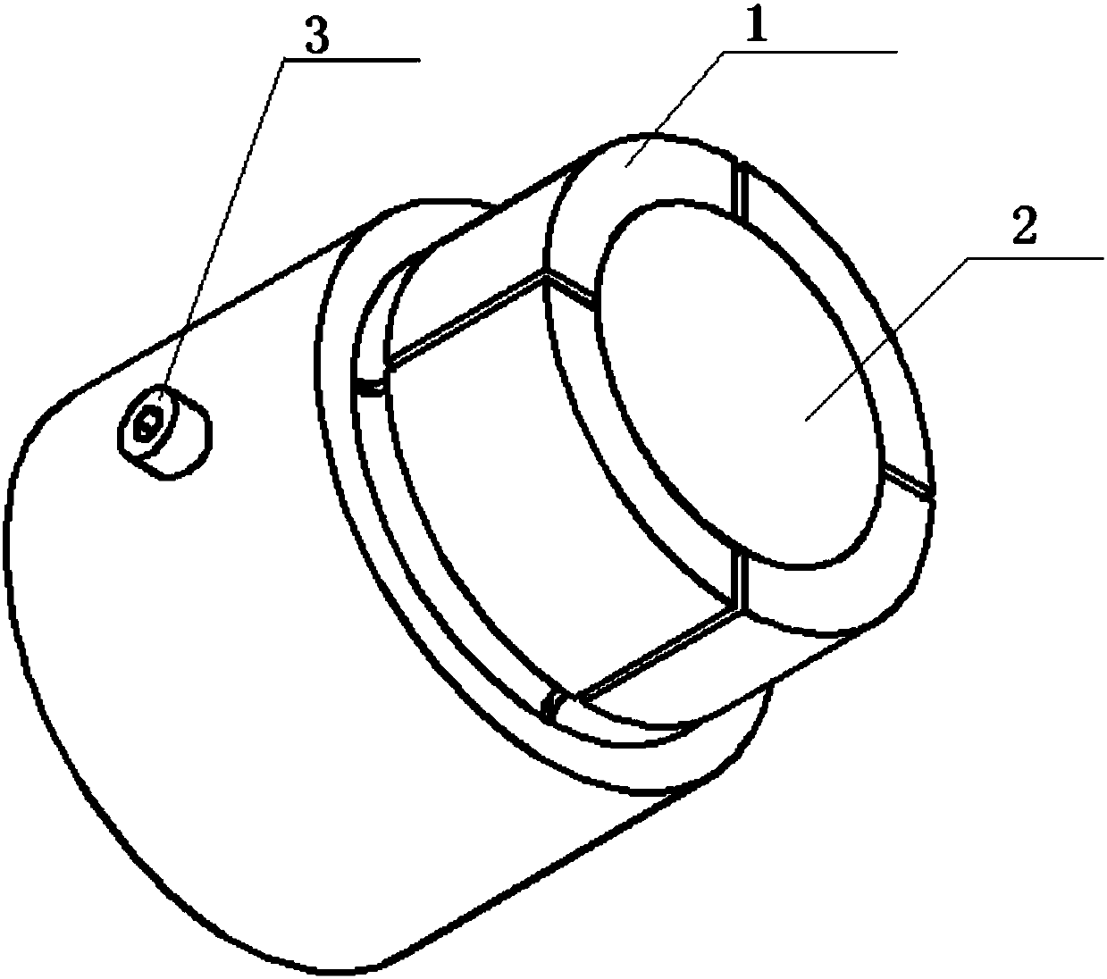
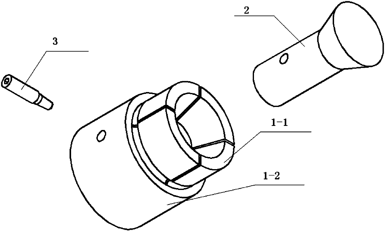
[0028] Such as figure 1 Shown is a schematic diagram of the overall structure of the quick-locking anti-stretching tire for positioning the workpiece on the inner hole and the end face. Cone top wire 3; wherein the cone mandrel 2 extends into the expansion sleeve 1 in the axial direction; the axial side wall of the expansion sleeve 1 is provided with a radial cylindrical through hole; the axial side wall of the cone mandrel 2 is provided with a radial Tapered groove; the size of the taper top screw 3 is matched with the cylindrical through hole of the expansion sleeve 1 and the tapered groove of the cone mandrel 2; after the taper mandrel 2 extends into the expansion sleeve 1 along the Radially pass through the cylindrical through hole of the expansion sleeve 1 and extend into the tapered groove of the tapered mandrel 2 to realize a fastening c...


PUM


Abstract

The invention discloses a quick locking anti-pull expanding tire of a workpiece being positioned by using an inner hole and an end face, and relates to the field of high-precision quick locking fixtures for numerically-controlled machine tools. The quick locking anti-pull expanding tire comprises an expanding sleeve, a tapered core shaft and a tapered jack screw, wherein the tapered core shaft stretches into the expanding sleeve in the axial direction; a radial cylindrical through hole is formed in the axial side wall of the expanding sleeve; a radial tapered groove is formed in the axial side wall of the tapered core shaft; the size of the tapered jack screw is fit with those of the cylindrical through hole of the expanding sleeve and the tapered groove of the tapered core shaft; after the expanding sleeve is assembled with the tapered core shaft, the tapered jack screw penetrates through the cylindrical through hole in the radial direction and stretches into the tapered groove of the tapered core shaft, thereby realizing fastening connection. With the adoption of the quick locking anti-pull expanding tire, high-precision quick locking of the workpiece being positioned by using the inner hole and the end face can be realized; clamping positioning can be carried out simply by using the inner hole and the end face; the processing of the excircle and the end face is not affected; the quick locking anti-pull expanding tire is simple and convenient to use; and on the premise of ensuring the positioning precision, the clamping efficiency is improved.

Description

technical field [0001] The invention relates to the field of high-precision fast locking fixtures for positioning workpieces on the end faces of inner holes, in particular to fast locking and anti-stretching tires for positioning workpieces on inner holes and end faces. Background technique [0002] In the CNC machining of precision parts, fast and high-precision clamping becomes the main factor determining the machining accuracy and efficiency. Especially for non-penetrating hollow, that is, blind cavity workpieces, when the inner hole and end face are used to position and process the shape, and the shape, inner hole, and end face have geometric accuracy requirements such as coaxiality and perpendicularity of not more than 0.01mm, the alignment of the part , Clamping is time-consuming and labor-intensive, and the accuracy is difficult to guarantee. [0003] At this stage, the finishing of the above parts, whether it is CNC lathe or CNC milling, is positioned by the inner h...

Claims


Application Information

Patent Timeline
Patent Type & Authority Patents(China)
IPC IPC(8): B23Q3/06B23B31/173
CPCB23B31/16158B23Q3/062
Inventor 李峰甄立张勇
Owner BEIJING INST OF AEROSPACE CONTROL DEVICES
Why Eureka
Try Eureka