
Underground working personnel emergency rescue guiding system and guiding method

An emergency rescue and operator technology, which is applied in earth-moving drilling, mining equipment, electrical components, etc., can solve the problems of difficult management of personnel entering the well, complicated mine tunnels, and untimely rescue, so as to reduce the number of casualties and improve emergency rescue. Efficiency and the effect of improving the level of safety in production

Active Publication Date: 2016-09-21
DALIAN LIAOGONG WEISEN OPTIC ELECTRONICS TECH
View PDF5 Cites 5 Cited by
  • Summary
  • Abstract
  • Description
  • Claims
  • Application Information

AI Technical Summary

Problems solved by technology

[0002] At present, it is difficult for mining enterprises to manage the personnel entering the well, and they cannot grasp the location information of the underground workers in real time. Once a dangerous accident occurs, due to the limitation of dispatching and communication methods, and the complexity of mine tunnels, it is often unclear at the moment when the mine underground accident occurs. The situation and location of the distribution of personnel, and the inability to provide timely escape guidance, resulting in untimely rescue and difficulty in minimizing the impact and loss of the accident
The reason for this problem is that the personnel positioning system and monitoring and monitoring system built by mining enterprises are independent of each other and there is no complete set of emergency rescue methods and related equipment

Method used


Image

  • Underground working personnel emergency rescue guiding system and guiding method
  • Underground working personnel emergency rescue guiding system and guiding method

Examples


Embodiment Construction

[0033] The technical solution of the present invention will be described in detail below in conjunction with the accompanying drawings and embodiments.

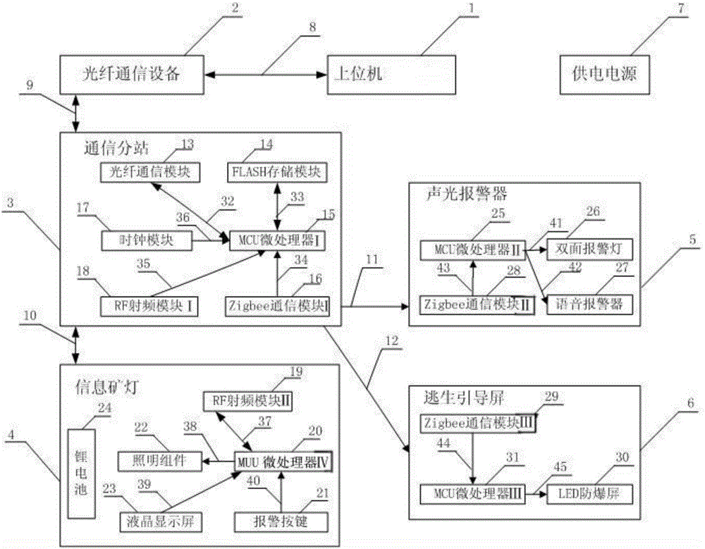
[0034] refer to figure 1 , the system consists of host computer 1, optical fiber communication equipment 2, communication substation 3, information miner's lamp 4, sound and light alarm 5, escape guidance screen 6 and power supply 7; power supply 7 is an underground 660 volt alternating current with explosion-proof function Turn on the 18 volt DC power supply. Optical fiber communication equipment 2 is composed of optical fiber switch, optical fiber, optical transceiver and twisted pair, responsible for data communication between communication substation 3 and host computer software system 1.

[0035] The communication substation 3 is composed of MCU microprocessor I15, RF radio frequency module I18, Zigbee communication module I16, FLASH storage module 14, clock module 17 and optical fiber communication module 13, and the i...


PUM


Abstract

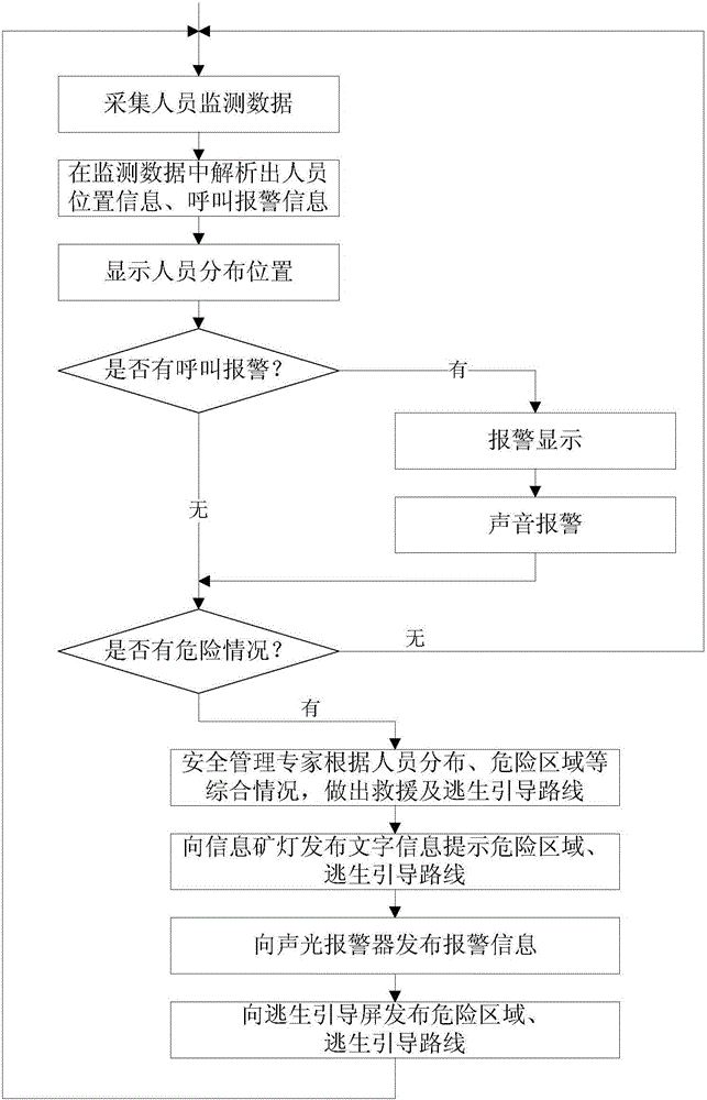
An underground working personnel emergency rescue guiding system and a guiding method are provided, so safety management personnel can timely learn about underground personnel distribution conditions, early warning can be timely send to underground people and an effectively escape route can be timely provided for underground personnel when danger happens, thus effectively reducing personnel casualty and economic losses, and improving mine enterprise safety production level; the guiding system comprises a host computer, a fiber communication device, a communication substation, an information miner light, an audible-visual annunciator, an escape guiding screen and a power supply; the guiding method comprises the following steps: the host computer receives people monitoring data from the communication substation through the fiber communication device, and sends short message data, alarm data and escape guiding data to the communication substation; the communication substation sends the short message data to the information miner light, and respectively transfers acousto-optic alarm data and escape guiding data to the audible-visual annunciator and escape guiding screen; the underground working personnel wear the information miner light, send communication codes identifying IDs to the communication substation, and receive the early warning information and the guiding route from the communication substation.

Description

technical field [0001] The invention relates to the field of emergency rescue of underground workers in industries such as mines and tunnel construction, in particular to an emergency rescue guidance system and guidance method for underground workers. Background technique [0002] At present, it is difficult for mining enterprises to manage the personnel entering the well, and they cannot grasp the location information of the underground workers in real time. Once a dangerous accident occurs, due to the limitation of dispatching and communication methods, and the complexity of mine tunnels, it is often unclear at the moment when the mine underground accident occurs. The situation and location of the distribution of personnel cannot provide timely escape guidance, resulting in untimely rescue, and it is difficult to minimize the impact and loss of the accident. The reason for this problem is that the personnel positioning system and monitoring and monitoring system built by m...

Claims


Application Information

Patent Timeline
IPC IPC(8): E21F17/18H04W84/18
CPCE21F17/18H04W84/18
Inventor 杜鹏李晗
Owner DALIAN LIAOGONG WEISEN OPTIC ELECTRONICS TECH
Learn More