
Device and method for measuring indicator diagram by electric parameters

A technology of electrical parameters and dynamometer diagrams, applied in construction and other directions, can solve the problems of inconvenient maintenance, high cost, large loss, etc., and achieve the effect of simplifying system composition and avoiding installation.

Pending Publication Date: 2016-09-21
HARBIN UNIV OF SCI & TECH +1
View PDF5 Cites 15 Cited by
  • Summary
  • Abstract
  • Description
  • Claims
  • Application Information

AI Technical Summary

Problems solved by technology

Its purpose is to overcome the above-mentioned disadvantages brought about by the application of displacement sensors and load sensors in the system, and use the method of measuring electrical parameters to indirectly obtain the relationship between the displacement of the suspension point and the load of the suspension point to draw the indicator diagram, and solve the problem of the sensor from the root cause. Problems such as high cost, large loss, inconvenient installation and maintenance, and poor real-time performance occurred in the measurement of the dynamometer diagram

Method used


Image

  • Device and method for measuring indicator diagram by electric parameters
  • Device and method for measuring indicator diagram by electric parameters
  • Device and method for measuring indicator diagram by electric parameters

Examples


Embodiment Construction

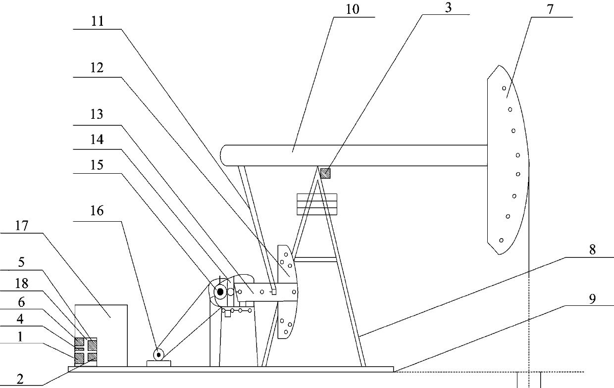
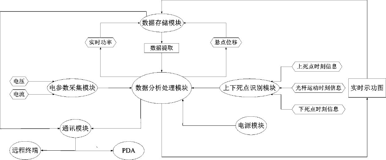
[0049] according to figure 1 As shown, the device (18) using electrical parameters to measure the dynamometer diagram includes a data analysis and processing module (1), a data storage module (2), an upper and lower dead center identification module (3) of the pumping unit, and an electrical parameter acquisition module (4). , a communication module (5), and a power module (6).

[0050] The data analysis and processing module (1), data storage module (2), electrical parameter acquisition module (4), communication module (5), and power supply module (6) are installed in the distribution box of the pumping unit, and the electrical parameter acquisition module ( 4) and the power module (6) are connected to the inlet end of the pumping unit motor.

[0051] When used as a measurement module, the identification module (3) of the upper and lower dead points of the pumping unit is composed of two micro switches, installed at the link between the beam and the support of the pumping un...


PUM


Abstract

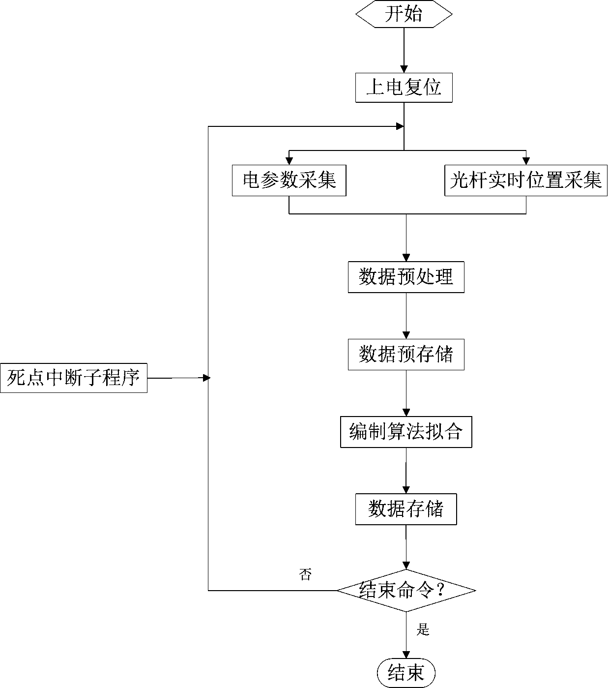
The invention relates to a device and method for measuring an indicator diagram by electric parameters. The device comprises a data analysis and processing module, a data storage module, an oil pumping unit upper and lower dead point recognition module, an electric parameter acquisition module, a communication module and a power supply module. Motor three-phase voltage and current parameters of an oil pumping unit are collected so that real-time power is obtained, real-time suspension point displacement is calculated or measured by combination of the upper and lower dead point recognition module, the relation between the power and the suspension point displacement is obtained, and finally the relation between the suspension point displacement of each moment in a complete stroke and suspension point load is obtained according to the relations of the torque and the power as well as the torque and the suspension point load, that is the indicator diagram is obtained. According to the device and method for measuring the indicator diagram by the electric parameters, the defect existing when a sensor measures the indicator diagram traditionally is effectively solved, and the indicator diagram is measured while the electric parameters are monitored. The structure is simple, the size is small, the device can be directly mounted in an oil well distribution box, the maintenance is convenient, and real-time data exchange and historical data reading of the device with a remote monitoring system of an oil filed can be realized.

Description

technical field [0001] The invention relates to a device and method for measuring a dynamometer diagram, in particular to a device and a method for measuring a dynamometer diagram by using electrical parameters. The utility model belongs to the technical field of petroleum testing instruments. Background technique [0002] As an important means to represent the working state of the oil well, the dynamometer diagram can fully reflect the operation status of the pumping unit and the exploitation of crude oil. The indicator map data is indispensable in inspecting the production of oil wells per unit time, tracking the dynamic situation of underground oil reservoir blocks, evaluating the development potential of oil well blocks, overall analysis and grasping the overall production capacity of oil fields. [0003] At present, the commonly used methods for measuring dynamometer diagrams can be roughly divided into two categories, namely, hand-held measurement and on-line measurem...

Claims


Application Information

Patent Timeline
IPC IPC(8): E21B47/009
CPCE21B47/009
Inventor 周封郝婷李隆刘小可崔博闻孟庆瑞邢方勃
Owner HARBIN UNIV OF SCI & TECH
Learn More