


Quick Research
Generate reliable direction feasibility study reports for your R&D in just a few steps.

Technical Q&A
Discover and master advanced knowledge NOW. Basics, ideas, possibilities, all at once.

Find Solutions
As an expert in R&D theories, this can generate solutions to your technical problems instantly.

Evaluate Feasibility
Analyze your overall solution with one click, know your potential R&D risks in advance.

Monitor Landscape
Get weekly tech updates, stay abreast of the latest tech innovations and key insights.
Sectional wood strip polishing device
A polishing device and wood line technology, applied in the direction of grinding drive device, grinding/polishing equipment, grinding workpiece support, etc., can solve the problems of labor-intensive, poor effect, etc., achieve high grinding efficiency, flexible use and adaptability strong effect
- Summary
- Abstract
- Description
- Claims
- Application Information
AI Technical Summary
Problems solved by technology
Method used
Image

Examples
Embodiment 1
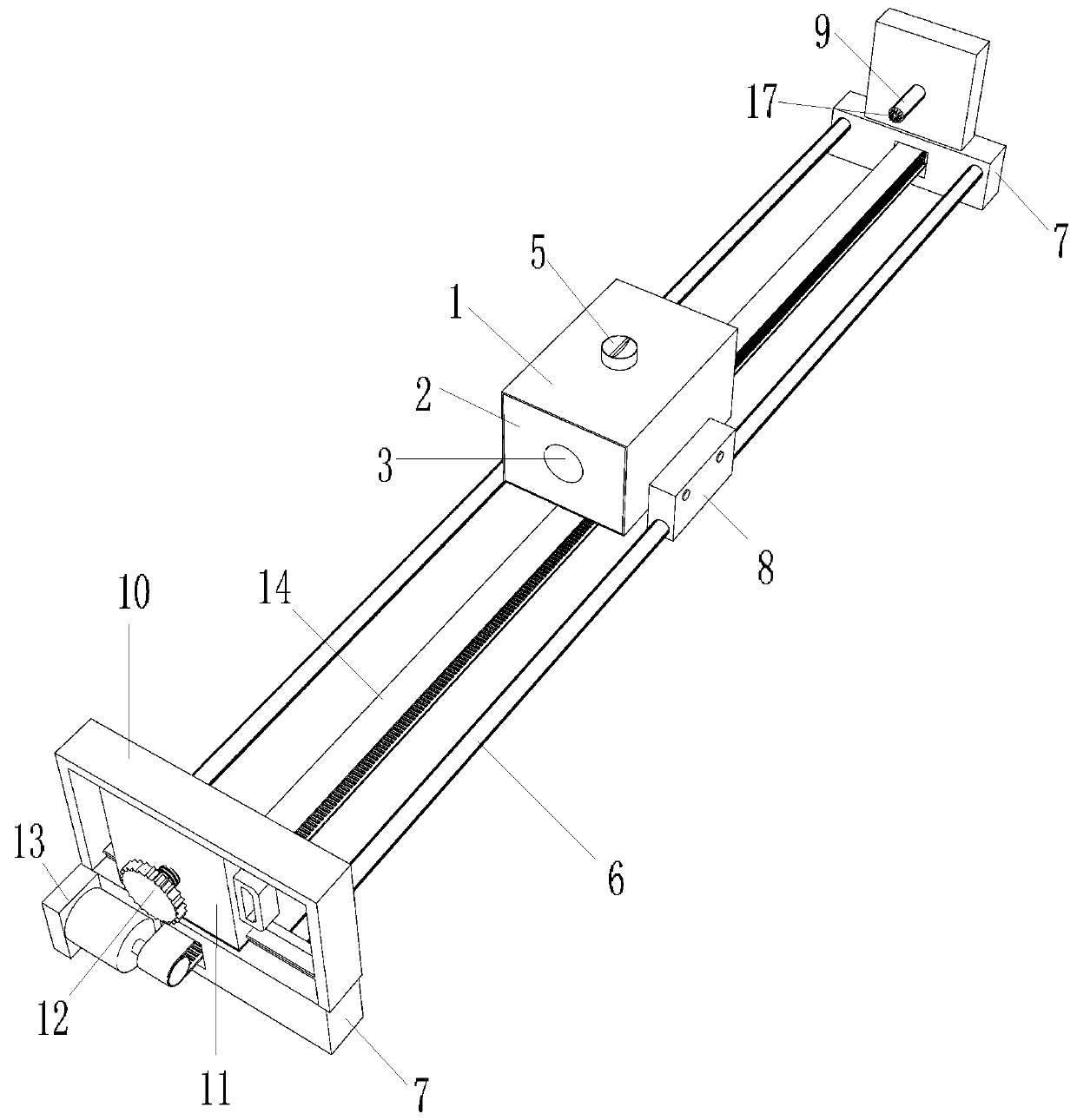
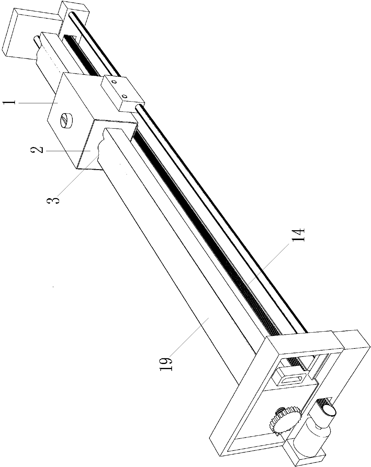
[0022] Such as Figure 1-3 As shown, the cross-sectional wood strip polishing device includes a polishing unit, a walking unit, and a supporting unit;
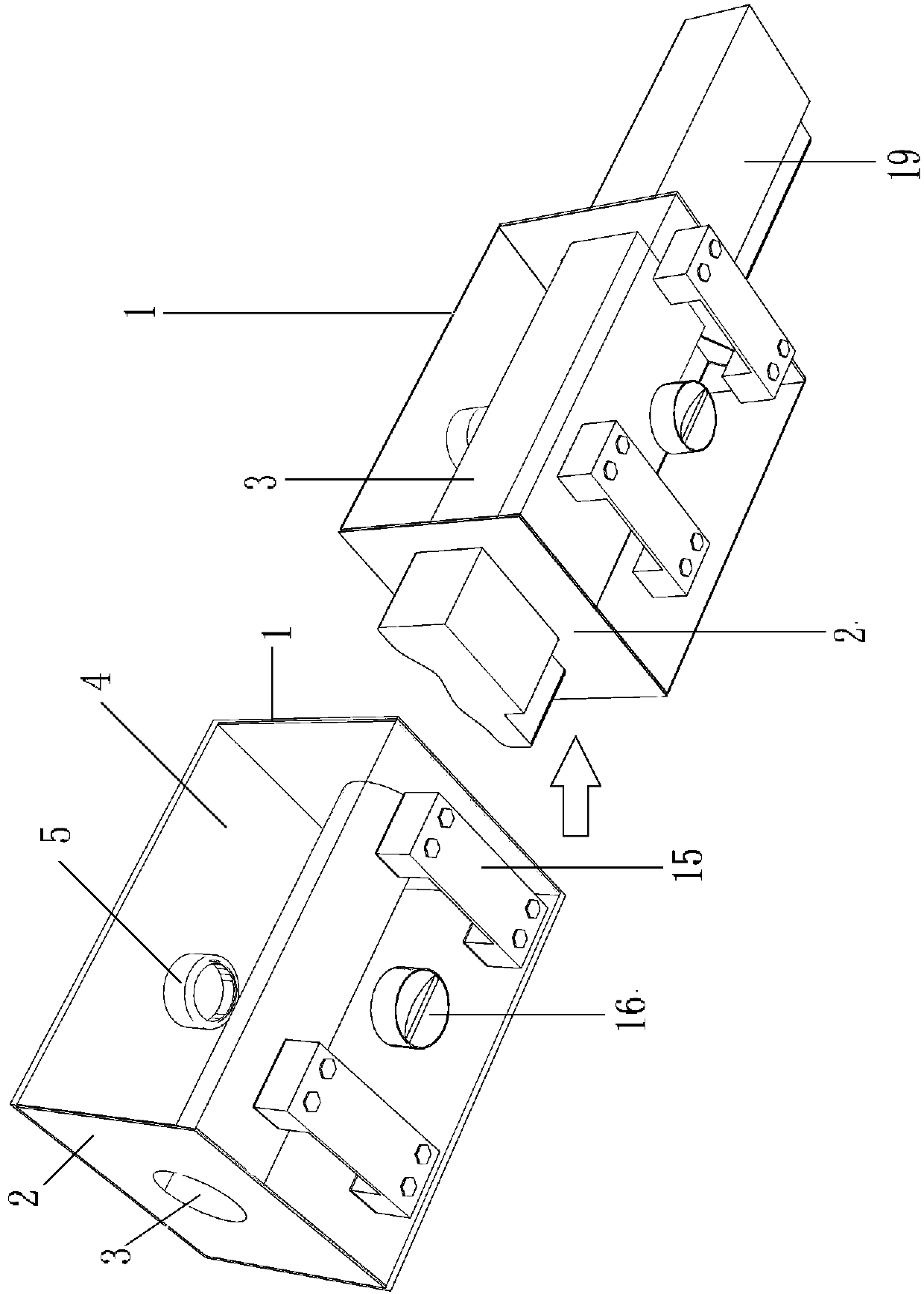
[0023] The shown polishing unit comprises a hard cylindrical shell 1, a soft elastic core cover 2 installed in the hard cylindrical shell 1; the soft elastic core cover 2 is dumbbell-shaped; The hard cylindrical shell 1 is sealed and connected; the center of the soft elastic core sleeve 2 is a polishing channel 3; the cavity between the hard cylindrical shell 1 and the soft elastic core sleeve 2 is the filling cabin 4; A hatch 5 is installed on the hard shell 1 at the top;
[0024] The support unit includes two guide support beams 6 arranged side by side in the middle, and support bases 7 fixed on the two ends of the two guide support beams 6; The slider 8 that is slidably connected to the support beam 6; the A positioning drill 9 is fixed on the rear support base 7, and the axis line of the A positioning drill 9 is aligned ...
Embodiment 2
[0031] The difference between the present embodiment and the first embodiment is: a cross-sectional wood molding polishing device, the bottom of the filling cabin 4 is equipped with a B hatch cover 16 on the hard cylinder shell 1; the filling cabin 4 is filled with soluble photosensitive resin; Quality tubular shell 1 is to have transparent organic glass material.
[0032] In the present embodiment, the filling fluid in the filling cabin 4 can adapt to the wood strips 19 of different cross-sectional shapes, but when it encounters an abrupt point, the shape of the polishing channel 3 may change because of the soft structure, and the abrupt point cannot be removed. Grinding off requires repeated manual grinding. This can be avoided by injecting soluble photosensitive resin: after the soluble photosensitive resin is injected, it is cured by irradiating the transparent hard cylindrical shell 1 with ultraviolet rays, so that the shape of the polishing channel 3 is fixed, so that th...
PUM
 Abstract
Description
Claims
Application Information
 - R&D Engineer
- R&D Manager
- IP Professional
- Industry Leading Data Capabilities
- Powerful AI technology
- Patent DNA Extraction
Browse by: Latest US Patents, China's latest patents, Technical Efficacy Thesaurus, Application Domain, Technology Topic, Popular Technical Reports.
© 2024 PatSnap. All rights reserved.Legal|Privacy policy|Modern Slavery Act Transparency Statement|Sitemap|About US| Contact US: help@patsnap.com