
Bevel gear milling fixture

A bevel gear and gear tooth technology, applied in the field of bevel gear milling fixtures, can solve problems such as unstable manufacturing quality, loss of chuck clamping force, and reduced product life, so as to improve machining accuracy and stability, and eliminate transmission Effects of improving gear backlash and rigidity conditions

Inactive Publication Date: 2016-09-21
王建法
View PDF0 Cites 0 Cited by
  • Summary
  • Abstract
  • Description
  • Claims
  • Application Information

AI Technical Summary

Problems solved by technology

[0002] At present, the manufacturing quality of bevel gears for three-jaw self-centering chucks is unstable, which makes the clamping force of the chucks lose, affects normal use, and reduces product life.
According to the test analysis, it is obtained that the gear teeth of the chuck bevel gear are out of tolerance, and the shape of the gear teeth is uneven
This is directly related to the processing method of jaw bevel gear teeth by using the existing milling fixture in the process of milling bevel gear tooth profile. The flaw in the design principle of the fixture structure inevitably leads to periodic process errors of the fixture during its work. , mainly due to the manufacturing error of each indexing gear, which causes periodic uneven rotation of the existing milling fixture to position the square tire, resulting in a deviation of the rotation angle of the processed tooth blank relative to the forming milling cutter, resulting in a tooth profile error

Method used


Image

  • Bevel gear milling fixture
  • Bevel gear milling fixture
  • Bevel gear milling fixture

Examples


Embodiment Construction

[0013] The present invention will now be further described in conjunction with specific examples, and the following examples are intended to illustrate the present invention rather than further limit the present invention.

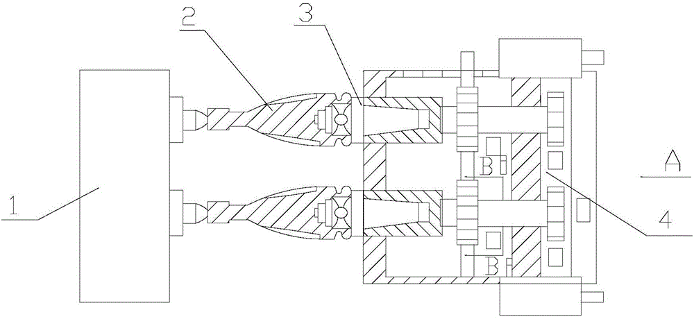
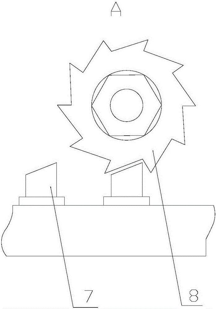
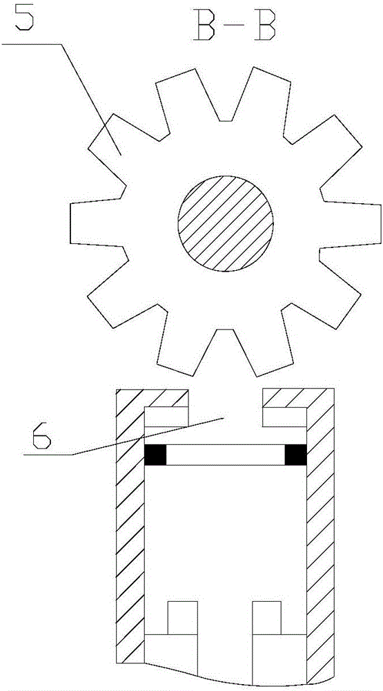
[0014] like Figure 1~3 As shown, a bevel gear milling fixture includes a positioning square tire 3, one end of the positioning square tire 3 is connected to one end of the bevel gear tooth blank 2, and the other end of the bevel gear tooth blank 2 is in contact with the hydraulically controlled tip device 1, The other end of the positioning square tire 3 is connected with a positioning indexing device 4. The positioning indexing device 4 includes a fine positioning indexing mechanism and a ratchet pawl auxiliary mechanism. The fine positioning indexing mechanism is composed of a toothed indexing plate 5 and a positioning Pin 6 forms, and ratchet pawl secondary mechanism comprises ratchet 8 and ratchet driving lever 7. Wherein, positioning square tire 3 l...


PUM


Abstract

The invention relates to the technical field of gear machining, in particular to a bevel gear milling fixture. The bevel gear milling fixture comprises positioning square tires; one ends of the positioning square tires are connected with one ends of bevel gear blanks, the other ends of the bevel gear blanks make contact with a centre device controlled hydraulically, and a positioning dividing device is connected to the other ends of the positioning square tires; the positioning dividing device comprises a fine positioning dividing mechanism and a ratchet wheel and pawl auxiliary mechanism; the fine positioning dividing mechanism is composed of a dividing plate uniform in tooth shape arrangement and a positioning pin; and the ratchet wheel and pawl auxiliary mechanism comprises a ratchet wheel and a pawl shift lever. According to the bevel gear milling fixture, the positioning square tires are directly connected with a positioning plate, the positioning piston is matched with tooth grooves of the dividing plate; thus, gaps of all levels of transmission gears of an original fixture are eliminated, and the distance between a machined workpiece and the positioning dividing device is decreased; and accordingly, the hard condition of the whole process system is greatly improved, and the machining precision and the stability of the workpiece are improved.

Description

technical field [0001] The invention relates to the technical field of gear processing, in particular to a bevel gear milling fixture. Background technique [0002] At present, the manufacturing quality of bevel gears for three-jaw self-centering chucks is unstable, which makes the clamping force of the chucks lose, affects normal use, and reduces product life. Through the test and analysis, it is obtained that the gear tooth equivalence accuracy of the chuck bevel gear is out of tolerance, and the shape of the gear teeth is uneven. This is directly related to the processing method of jaw bevel gear teeth by using the existing milling fixture in the process of milling bevel gear tooth profile. The flaw in the design principle of the fixture structure inevitably leads to periodic process errors of the fixture during its work. , mainly due to the manufacturing error of each indexing gear, which causes the existing milling jig to position the square tire to produce periodic un...

Claims


Application Information

Patent Timeline
Patent Type & Authority Applications(China)
IPC IPC(8): B23F23/06B23F5/24
CPCB23F23/06B23F5/24
Inventor 王建法王继纯
Owner 王建法
Learn More