
Prestress-steel-wire-rope-bending-shearing-reinforced concrete T beam and reinforcing method thereof

A concrete and steel wire rope technology, which is applied in building maintenance, construction, building construction, etc., can solve the problems of increasing the self-weight of original components, peeling damage of anchorage ends, and insufficient shear resistance, so as to improve the overall bearing capacity and reduce the influence of structural self-weight , to avoid the effect of stress hysteresis effect

Inactive Publication Date: 2016-09-14
JIANGXI GANYUE EXPRESSWAY +2
View PDF9 Cites 11 Cited by
  • Summary
  • Abstract
  • Description
  • Claims
  • Application Information

AI Technical Summary

Problems solved by technology

[0004] As far as a single reinforcement technology is concerned, these reinforcement technologies have the disadvantages of increasing the self-weight of the original component, there is a stress hysteresis effect between the reinforcement material and the original component, it is easy to find the peeling damage of the anchorage end, the construction is complicated, and the cost is high;
[0005] The shear performance of the original component after bending resistance is slightly insufficient, and it may be prone to shear failure, while the bending resistance of the original component after shear strengthening is also insufficient, and it may be prone to bending failure

Method used


Image

  • Prestress-steel-wire-rope-bending-shearing-reinforced concrete T beam and reinforcing method thereof
  • Prestress-steel-wire-rope-bending-shearing-reinforced concrete T beam and reinforcing method thereof

Examples


Embodiment Construction

[0035] The present invention will be further described below in conjunction with the accompanying drawings.

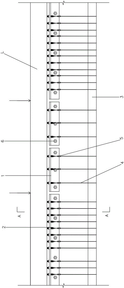
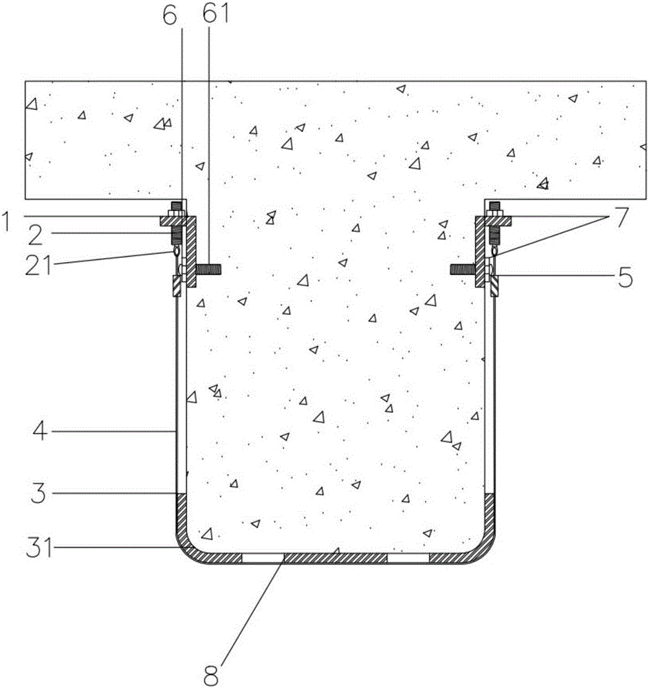
[0036] Such as figure 1 , figure 2 A prestressed steel wire rope bending-shear reinforced concrete T-beam shown includes a reinforcement system arranged on the concrete T-beam. The reinforcement system includes a steel wire rope 4, a plurality of bending-resistant steel plates 8 installed at the bottom of the concrete T-beam L and horizontally fixed A plurality of angle steels 1 on both sides of the web plate of the concrete T-beam L has a plurality of bolt holes along its length direction on the other side of each angle steel 1, and an adjustable bolt 2 is arranged in each bolt hole, and one end of the adjustable bolt 2 is arranged After the ring 21 and the steel wire rope 4 go around the bottom of the beam, the two ends respectively pass through the corresponding ring 21 and are tensioned. A protection system is also provided outside the reinforcement system. A ho...


PUM


Abstract

The invention discloses a prestress-steel-wire-rope-bending-shearing-reinforced concrete T beam. The prestress-steel-wire-rope-bending-shearing-reinforced concrete T beam comprises a reinforcing system arranged on the concrete T beam. The reinforcing system comprises steel wire ropes, a plurality of bending-resistant reinforcing steel plates arranged at the bottom of the concrete T beam and a plurality of angle steels horizontally fixed to the two sides of a web plate of the concrete T beam; a plurality of bolt holes are formed in the other edges of all the angle steels in the length direction of the angle steels, adjustable bolts are arranged in all the bolt holes, circular rings are arranged at one ends of the adjustable bolts, and after the steel wire ropes are wound around the beam bottom, the two ends penetrate through corresponding circular rings respectively and are tensioned; a protection system is further arranged on the outer side of the reinforcing system. In the reinforcing process, prestress is applied to the steel wire ropes through the adjustable bolts, a specially-made tensioning apparatus does not need to be adopted, construction is convenient and fast, construction efficiency is greatly improved, the prestress is applied to the steel wire ropes, the stress hysteresis effect is avoided, and the reinforcing effect and the whole bearing capacity are improved; construction cost is low, construction is easy and convenient, the influence on structure weight is small, and the excellent structural performance and economic benefits are achieved.

Description

technical field [0001] The invention relates to the technical field of reinforced concrete beam reinforcement, in particular to a prestressed steel wire rope bending shear reinforced concrete T beam and a reinforcement method thereof. Background technique [0002] With the development of time, the problems of maintenance and reinforcement of houses, bridges and other buildings have become increasingly prominent due to imperfect design theories, material aging, overloading, construction quality defects, structural part damage, and changes in use functions. The commonly used flexural and shear strengthening technologies for reinforced concrete beams mainly include enlarging section method, bonding steel reinforcement method, pasting fiber composite material reinforcement method, steel strand mesh-polymer mortar reinforcement method, external prestressed reinforcement method, etc. . [0003] The existing reinforcement methods have the following problems: [0004] As far as a ...

Claims


Application Information

Patent Timeline
Patent Type & Authority Applications(China)
IPC IPC(8): E04G23/02E04G21/12
CPCE04G21/12E04G23/02E04G23/0218
Inventor 吴刚吁新华蒋剑彪许心怡
Owner JIANGXI GANYUE EXPRESSWAY
Learn More