Structure of reinforced circular steel tube confined concrete column-beam joint

A technology for constraining concrete and reinforced concrete beams, applied in the direction of building structure, construction, etc., can solve problems such as failure, difficulty in meeting strong joints, weak components, etc., to improve bearing capacity and deformation performance, avoid local instability, and simple operation. Effect

Inactive Publication Date: 2016-09-14
ARCHITECTURAL DESIGN & RES INST OF SOUTH CHINA UNIV OF TECH
View PDF6 Cites 2 Cited by
  • Summary
  • Abstract
  • Description
  • Claims
  • Application Information

AI Technical Summary

Problems solved by technology

[0003] Although steel pipe-confined reinforced concrete structures have many advantages, at present, when steel pipe-confined reinforced concrete columns are applied, the beam-column joint area is still a common reinforced concrete beam-column joint structure. If no strengthening measures are taken, the concrete in the joint area is less constrained than the column body. The bearing capacity of the joints may be weaker than that of the column body, making it difficult to meet the design principle of "strong joints, weak members"
When subjected to earthquake action, the structure itself may have a potential safety hazard that the node area will be destroyed before the column body

Method used


Image

  • Structure of reinforced circular steel tube confined concrete column-beam joint
  • Structure of reinforced circular steel tube confined concrete column-beam joint

Examples


Embodiment

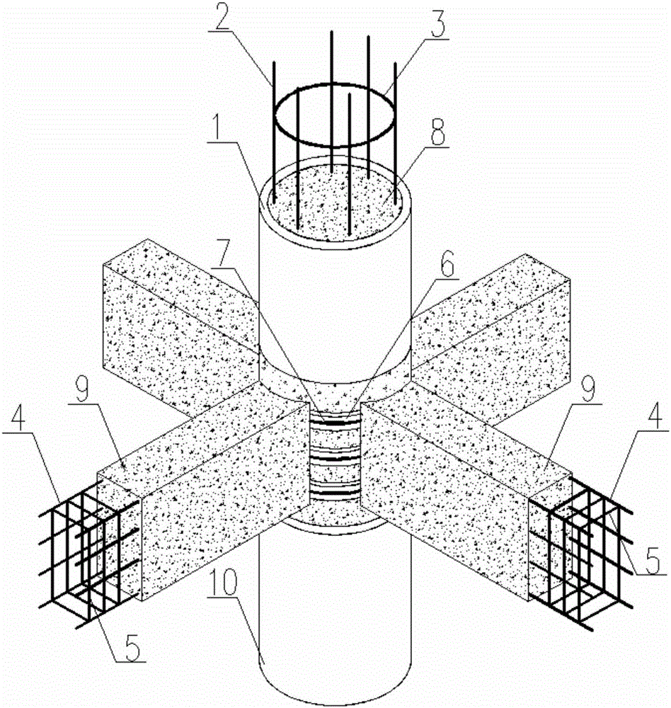
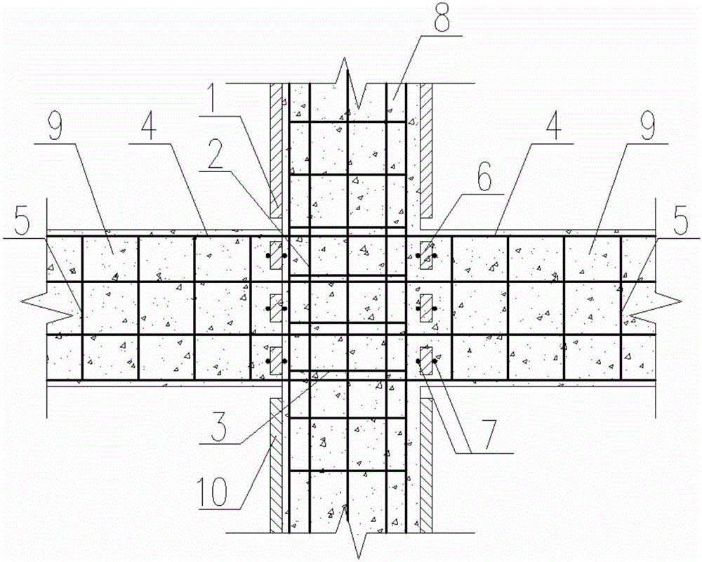
[0046]Two reinforced concrete beams perpendicular to each other, the intersection of the steel pipe confined concrete column and the two reinforced concrete beams is the node. The diameters of the upper column steel pipe 1 , the lower column steel pipe 10 and the steel ring 6 in the node area are all 500 mm, and the wall thickness is 8 mm. The heights of the steel rings 6 in the three node areas from top to bottom are 50mm, 200mm and 50mm respectively. Both reinforced concrete beams are 250mm wide and 500mm high. Steel ring 6 in the node area, steel pipe 1 for the upper column body and steel pipe 10 for the lower column body are all made of Q345 steel, and the strength grade of the column concrete is C50.

[0047] The reinforced concrete beam is composed of beam longitudinal bars 4 , beam stirrups 5 and beam concrete 9 . The beam longitudinal bars 4 are distributed as two HRB400 steel bars with a diameter of 14mm in the upper part, two HRB400 steel bars with a diameter of 14...


PUM

PropertyMeasurementUnit
diameteraaaaaaaaaa
thicknessaaaaaaaaaa
diameteraaaaaaaaaa

Abstract

The invention discloses a structure of a reinforced circular steel tube confined concrete column-beam joint. According to the structure, joint area steel rings are arranged between an upper column body steel tube and a lower column body steel tube; anti-shear rings are welded to the inner surfaces and the outer surfaces of the joint area steel rings respectively; longitudinal beam bars penetrate through a joint area through gaps formed among the joint area steel rings and a gap formed between the joint area steel rings and the upper column body steel tube or a gap formed between the joint area steel rings and the lower column body steel tube; the longitudinal beam bars and beam stirrups are bound together to form steel bar concrete beam steel bar cages; longitudinal column bars penetrate through the upper column body steel tube, the joint area steel rings and the lower column body steel tube to be bound together with column stirrups to form tube-inside steel bar cages of the upper column body steel tube, the lower column body steel tube and the joint area steel rings; beam concrete is poured into the steel bar concrete beam steel bar cages; column concrete is poured into the tube-inside steel bar cages. According to the structure form of the steel tube confined concrete column-beam joint, manufacture is flexible, and the advantage of improving the axial compression resistance, the deformation performance and the seismic resistance of the joint area is achieved.

Description

technical field [0001] The invention relates to the field of building structural components, in particular to a structural form of reinforced circular steel pipe-constrained concrete column-beam joints. Background technique [0002] The steel pipe confined concrete structure is a new type of composite structure that has emerged in recent years. The steel pipe confined reinforced concrete column has outstanding advantages such as high bearing capacity, strong elastic-plastic deformation capacity, good energy dissipation performance, convenient construction of beam-column joints, and saving formwork. It will be widely used in high-rise and super high-rise building structures, large-scale heavy-duty complex industrial plants and long-span bridge structures, and will achieve good economic and social benefits. [0003] Although steel pipe-confined reinforced concrete structures have many advantages, at present, when steel pipe-confined reinforced concrete columns are applied, the...

Claims


Application Information

Patent Timeline
Patent Type & Authority Applications(China)
IPC IPC(8): E04B1/30E04B1/58
CPCE04B1/30
Inventor 王帆许晓峰韦宏黄昌辉
Owner ARCHITECTURAL DESIGN & RES INST OF SOUTH CHINA UNIV OF TECH
Why Eureka
Try Eureka