
Pressure controller for injection molding machine

An injection molding machine and pressure control technology, which is applied in the field of pressure control devices, can solve the problems of cost increase and achieve the effect of preventing stress deformation

Active Publication Date: 2016-09-14
FANUC LTD
View PDF11 Cites 0 Cited by
  • Summary
  • Abstract
  • Description
  • Claims
  • Application Information

AI Technical Summary

Problems solved by technology

However, since a special unit such as a pressure sensor is provided inside the mold, there is a problem of cost increase

Method used


Image

  • Pressure controller for injection molding machine
  • Pressure controller for injection molding machine
  • Pressure controller for injection molding machine

Examples


Embodiment Construction

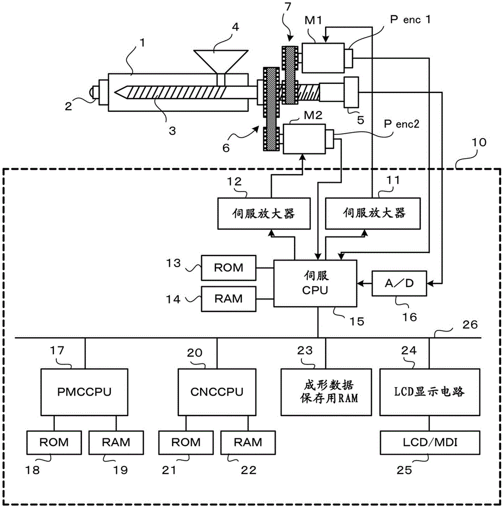
[0035] below, with Figure 1 Embodiments of the present invention will be described together.

[0036] figure 1 It is a schematic configuration diagram of an injection molding machine and a control device for controlling the injection molding machine. A nozzle 2 is attached to the front end of the cylinder 1 into which the screw 3 is inserted, and a hopper 4 for supplying resin pellets to the cylinder 1 is attached to the side of the rear end of the cylinder 1 . The screw 3 is driven in the axial direction by the injection servo motor M1, the transmission mechanism, and the conversion mechanism 7 that converts the rotational motion of the bolt / nut etc. into a linear motion as a driving unit for driving the screw 3 in the axial direction. Injection and back pressure control. In addition, the screw 3 is rotationally driven by a transmission mechanism 6 composed of a servo motor M2 as a rotational drive means for rotating the screw 3 , a belt, a pulley, and the like.

[0037] ...


PUM


Abstract

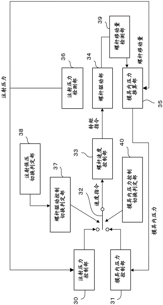
A pressure controller for an injection molding machine capable of reducing variations of pressure in a mold in molding cycles and providing molded articles of stable quality is provided. The pressure controller includes an in-mold pressure estimation unit for estimating a pressure in the mold based on an injection pressure detected with an injection pressure detection unit, and an amount of movement of a screw detected with a screw movement amount detection unit, and an in-mold pressure control unit for controlling such that the estimated in-mold pressure becomes a set in-mold pressure after the pressure control is performed in a dwell step with an injection pressure control unit.

Description

technical field [0001] The invention relates to an injection molding machine, in particular to a pressure control device of the injection molding machine. Background technique [0002] In the coaxial screw type injection molding machine, the following steps are performed: the screw in the heating cylinder is rotated while the screw is retracted to measure the molten resin to the front end of the heating cylinder, and then the screw is advanced to the metal. Injection process and pressure holding process of filling the mold with molten resin. [0003] In the injection process, the molten resin in the heating cylinder is filled into the mold by advancing the screw based on the preset injection stroke and injection speed. Then, when it advances to the injection / pressure holding switching position, it switches from the injection process to the pressure holding process. In the holding process, the pressure is controlled based on the preset holding pressure and the set time, so ...

Claims


Application Information

Patent Timeline
Patent Type & Authority Applications(China)
IPC IPC(8): B29C45/77
CPCB29C45/77B29C2945/76498B29C2045/776B29C2945/76006B29C2945/76096B29C2945/76187B29C2945/76381B29C2945/76595B29C2945/76665B29C2945/76859B29C2945/76862B29C2945/76969B29C45/0025B29C45/1774B29C45/50B29C45/768
Inventor 丸山淳平
Owner FANUC LTD
Learn More