Method and device for generating dynamic image code
A dynamic image and generation device technology, applied in the field of image codes, can solve the problems of technical implementation difficulty and high cost, the information carried is fixed, and cannot be divided into multiple parts, etc., so as to achieve technical implementation difficulty and low cost, and flexible change , the effect of small occupied size
- Summary
- Abstract
- Description
- Claims
- Application Information
AI Technical Summary
Problems solved by technology
Method used
Image
Examples
Embodiment 1
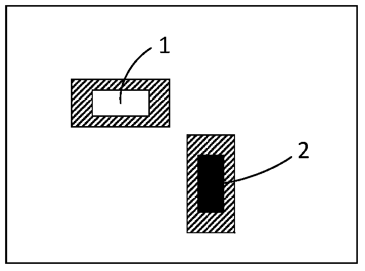
[0076] Such as figure 1 shown by the display unit D 1 , display unit D 2 Composed of a set of display units to display dynamic image codes, D 1 for LED 1, D 2 For LED 2, each LED can be switched between two display states of "on" and "off", where white indicates that the LED is "on", and black indicates that the LED is "off". 1 Indicates that the display state is "bright", use S 2 Indicates that the display status is "off".
[0077] From display state S 1 switch to S 2 , or from display state S 2 switch to S 1 For 1-step switching, from display state S 1 switch to S 1 , or from display state S 2 switch to S 2 Switch to 0 steps.
[0078] For the set of display units, there are four display modes, such as Figures 1 to 4 shown, respectively with S 1 S 1 , S 2 S 1 , S 1 S 2 , S 2 S 2 To represent.
[0079] In each period, the display mode of the set of display units is switched once, and according to the display mode before and after the switch, more specif...
Embodiment 2
[0120] Such as Figure 5 or 6, through the display unit D 1 , display unit D 2 , display unit D 3 A set of display units is formed to display dynamic image codes.
[0121] Each display unit is an area composed of multiple pixels on the display screen, where the display unit D 1 For area 4, D 2 For area 5, D 3 for zone 6. Each display unit can be switched among three display states of "red", "green" and "blue", respectively with S 1 , S 2 , S 3 To indicate that for the display unit set, there are 27 display modes:
[0122] S 1 S 1 S 1 , S 1 S 1 S 2 , S 1 S 1 S 3 , S 1 S 2 S 1 , S 1 S 2 S 2 , S 1 S 2 S 3 , S 1 S 3 S 1 , S 1 S 3 S 2 , S 1 S 3 S 3 ,
[0123] S 2 S 1 S 1 , S 2 S 1 S 2 , S 2 S 1 S 3 , S 2 S 2 S 1 , S 2 S 2 S 2 , S 2 S 2 S 3 , S 2 S 3 S 1 , S 2 S 3 S 2 , S 2 S 3 S 3 ,
[0124] S 3 S 1 S 1 , S 3 S 1 S 2 , S 3 S 1 S 3 , S 3 S 2 S 1 , S 3 S 2 S 2 , S 3 S 2 S 3 , S 3 S 3 S 1 , S 3 S 3...
Embodiment 3
[0174] Such as Figure 7 As shown, the set of display units consists of a display unit D 1The display unit is a color light-emitting diode 3. Theoretically, the color diode can emit light of countless colors, that is, it can have countless display states, but usually only select a part of the display that is easy to be scanned and recognized by the information receiving end according to needs. State, select "red", "green", "blue", "off" four display states in this embodiment, use S 1 , S 2 , S 3 , S 4 To indicate that these states are easy to identify and easy to control with a single-chip microcomputer. Then the set of display units has four display modes in total. In order to distinguish them from the display states, use {S 1}, {S 2}, {S 3}, {S 4}To represent.
[0175] In each cycle, the display mode of the display unit set is switched once, and the following four signals are defined according to the number of steps for switching the display state of each display un...
PUM
 Abstract
Description
Claims
Application Information
 - R&D
- Intellectual Property
- Life Sciences
- Materials
- Tech Scout
- Unparalleled Data Quality
- Higher Quality Content
- 60% Fewer Hallucinations
Browse by: Latest US Patents, China's latest patents, Technical Efficacy Thesaurus, Application Domain, Technology Topic, Popular Technical Reports.
© 2025 PatSnap. All rights reserved.Legal|Privacy policy|Modern Slavery Act Transparency Statement|Sitemap|About US| Contact US: help@patsnap.com


