A self-powered circuit for switching circuits

A switching circuit and self-powered technology, which is applied in the direction of irreversible AC power input conversion to DC power output, etc., can solve the problems of large transformer volume, reduced chip efficiency, and increased application cost, so as to avoid the use of high-voltage devices, simple structure, The effect of energy self-harvesting

Inactive Publication Date: 2018-06-19
UNIV OF ELECTRONICS SCI & TECH OF CHINA
View PDF5 Cites 0 Cited by
  • Summary
  • Abstract
  • Description
  • Claims
  • Application Information

AI Technical Summary

Problems solved by technology

However, this method requires a larger transformer volume and increases the overall application cost
In addition, the energy of these two methods comes from the total power supply, which requires additional power consumption, resulting in a reduction in chip efficiency

Method used


Image

  • A self-powered circuit for switching circuits
  • A self-powered circuit for switching circuits
  • A self-powered circuit for switching circuits

Examples


Embodiment Construction

[0011] The present invention is described in detail below in conjunction with accompanying drawing:

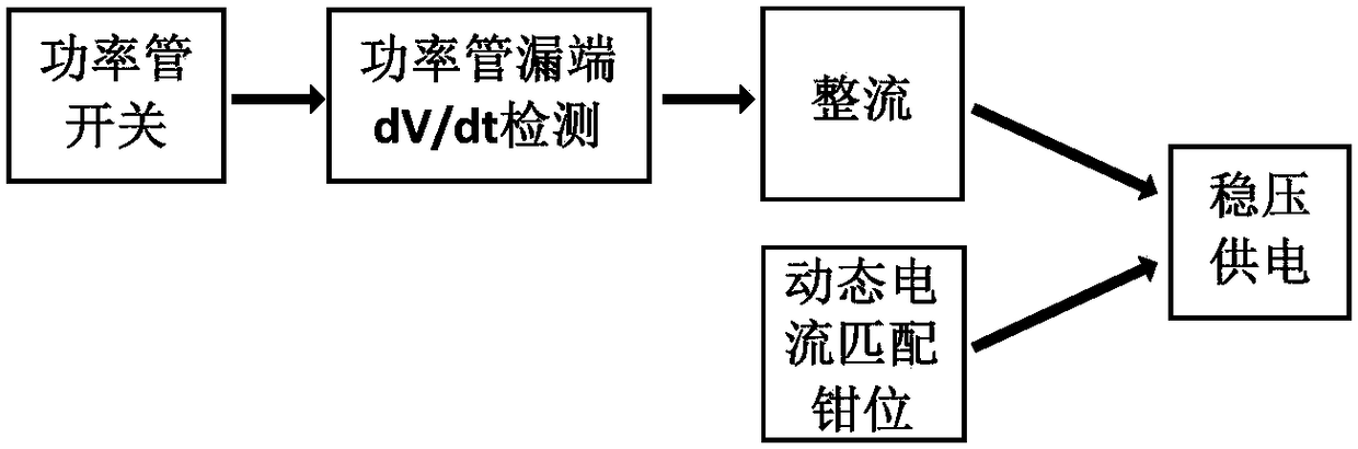
[0012] The system schematic diagram of the present invention is as figure 1 shown. When the power tube is switched on and off, the voltage at the drain end of the power tube will change with time. By detecting the dv / dt of the drain end when the power tube is turned off, the current required for the system power supply is collected, and then through the rectification and dynamic current matching clamp module to achieve stability. voltage supply. The following will combine the circuit to analyze the system in detail.

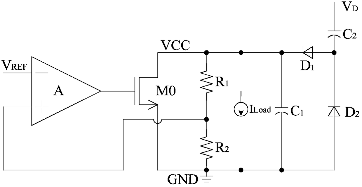
[0013] The topological structure diagram of the present invention is as figure 2 As shown, it includes operational amplifier, power tube M0, first voltage dividing resistor R1, second voltage dividing resistor R2, load current source ILoad, first capacitor C1, second capacitor C2, first diode D1, second two Diode tube D2; the negative phase input terminal of...


PUM


Abstract

The invention belongs to the technical field of electronic circuits, and in particular relates to a self-supply circuit for switching circuits. The circuit of the present invention includes an operational amplifier, a power transistor M0, a first voltage dividing resistor R1, a second voltage dividing resistor R2, a load current source ILoad, a first capacitor C1, a second capacitor C2, a first diode D1, a second capacitor C2 Two D2; the negative phase input terminal of the operational amplifier is connected to the reference voltage, and its output terminal is connected to the gate of the power tube M0; the drain of the power tube M0 is connected to the power supply, and the source is grounded; the positive phase input terminal of the operational amplifier is connected to the first divided voltage Resistor R1; the first voltage dividing resistor R1 is connected to the drain of the power tube M0, and the second voltage dividing resistor R2 is grounded; the drain of the power tube M0 is connected to the negative pole of the first diode D1, and the positive pole of the second diode D2 is grounded ; The anode of the first diode D1 is connected to the drain voltage of the power transistor M0. The structure of the present invention has the advantages of simple structure, self-collection of energy, high overall system efficiency, avoiding the use of high-voltage devices and low cost.

Description

technical field [0001] The invention belongs to the technical field of high-voltage switch circuits, and in particular relates to a self-power supply circuit for switch circuits. Background technique [0002] In high-voltage power conversion circuits, such as Flyback and Buck topology circuits, the switching of the power switching tube is controlled by a feedback signal to achieve energy transfer. There are usually two ways to supply power to the control part of the chip: 1. Directly obtain DC voltage from the main power supply to supply power to the IC. This method usually requires more high-voltage devices, which reduces the integration of the chip. 2. Using the auxiliary winding, the output voltage is used to supply power to the chip through the transformer principle. However, this method requires a larger transformer volume and increases the overall application cost. In addition, the energy of these two methods comes from the general power supply, which needs to consu...

Claims


Application Information

Patent Timeline
Patent Type & Authority Patents(China)
IPC IPC(8): H02M7/04
CPCH02M7/04
Inventor 周泽坤董瑞凯张家豪石跃王卓张波
Owner UNIV OF ELECTRONICS SCI & TECH OF CHINA
Why Eureka
Try Eureka