
Bus capacitor discharge method, controller and dcdc converter

A bus capacitor and converter technology, applied in the direction of DC power input conversion to DC power output, AC power input conversion to DC power output, electrical components, etc., can solve problems such as the need for additional discharge circuits

Active Publication Date: 2018-11-06
SUNGROW POWER SUPPLY CO LTD
View PDF5 Cites 0 Cited by
  • Summary
  • Abstract
  • Description
  • Claims
  • Application Information

AI Technical Summary

Problems solved by technology

[0006] In view of this, the present invention provides a bus capacitor discharge method, a controller, a DCDC converter and an inverter, to solve the problem that an additional discharge circuit is required in the prior art

Method used


Image

  • Bus capacitor discharge method, controller and dcdc converter
  • Bus capacitor discharge method, controller and dcdc converter
  • Bus capacitor discharge method, controller and dcdc converter

Examples


Embodiment Construction

[0047] The following will clearly and completely describe the technical solutions in the embodiments of the present invention with reference to the accompanying drawings in the embodiments of the present invention. Obviously, the described embodiments are only some, not all, embodiments of the present invention. Based on the embodiments of the present invention, all other embodiments obtained by persons of ordinary skill in the art without making creative efforts belong to the protection scope of the present invention.

[0048] The invention provides a bus capacitor discharge method to solve the problem of needing an additional discharge circuit in the prior art.

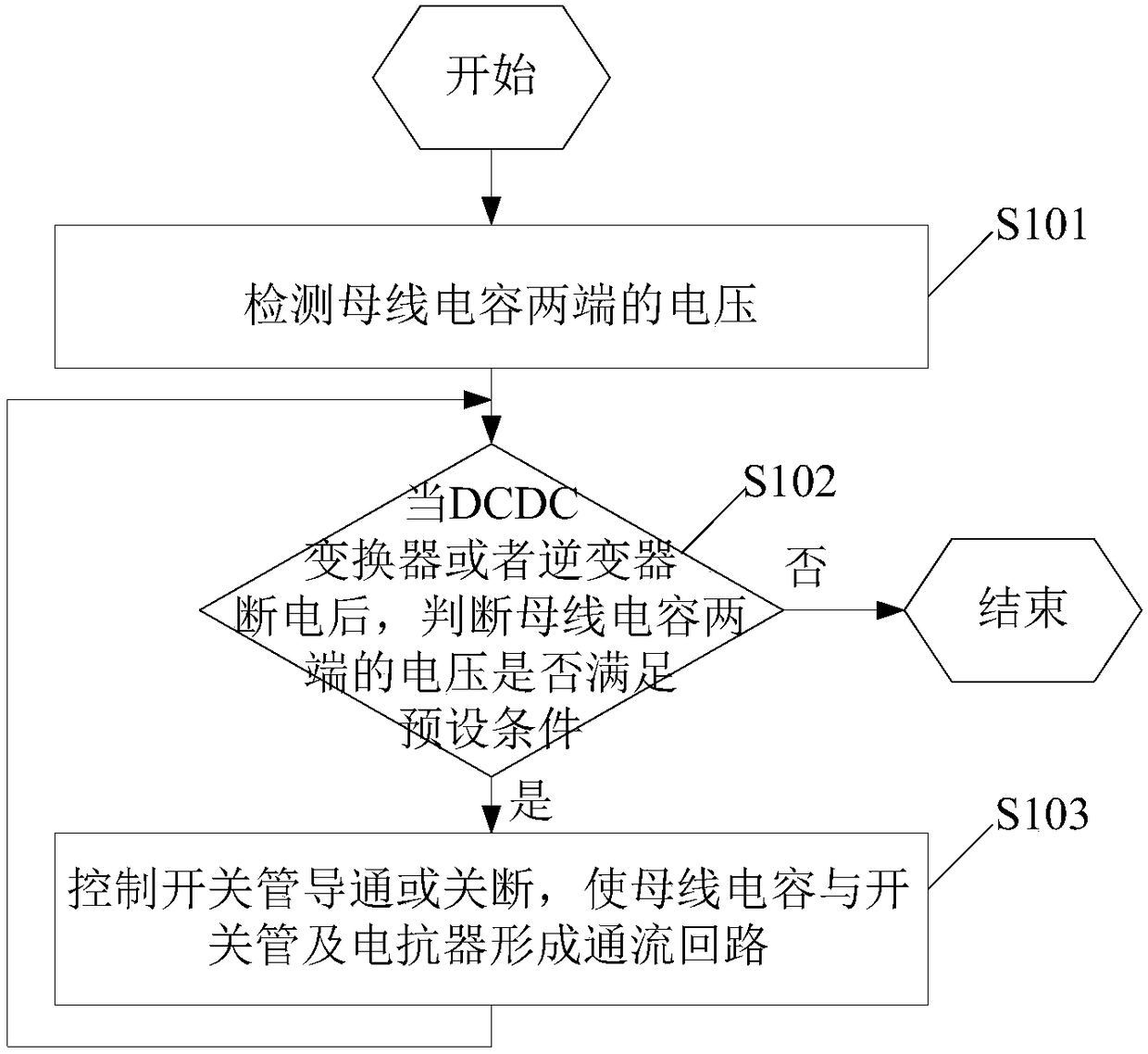
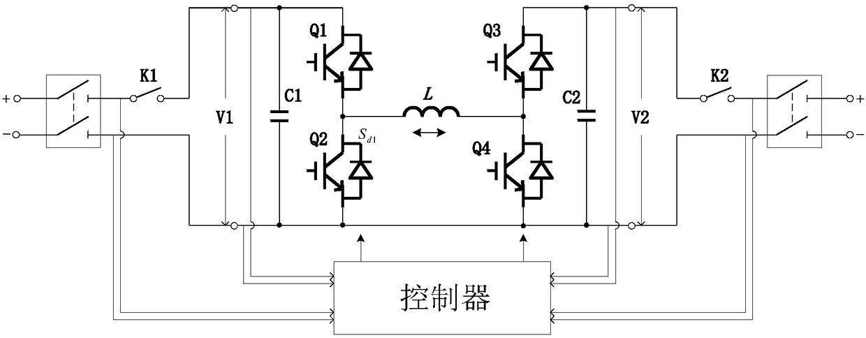
[0049] Specifically, the bus capacitor discharging method is applied to a controller of a DCDC converter or an inverter, and the DCDC converter or inverter includes: a bus capacitor, a switch tube, and a reactor; the bus capacitor discharging method is as follows: figure 1 shown, including:

[0050] S101. Detect th...


PUM


Abstract

The present application provides a bus capacitor discharge method, a controller, a DCDC converter and an inverter. After the DCDC converter or the inverter is powered off, when the detected bus capacitance of the DCDC converter or the inverter is determined and detected When the voltage at both ends meets the preset condition, the switch tube of the DCDC converter or the inverter is controlled to be turned on or off, so that the bus capacitance and the reactance of the switch tube and the DCDC converter or the inverter are connected. The DC-DC converter forms a current loop until the voltage across the bus capacitor does not meet the preset conditions; after the DCDC converter or the inverter is powered off, the discharge function of the bus capacitor is realized, and there is no need for additional The discharge circuit solves various problems caused by the need for additional discharge circuits in the prior art.

Description

technical field [0001] The invention relates to the technical field of power conversion, in particular to a method for discharging a bus capacitor, a controller and a DC-DC converter. Background technique [0002] At present, after various DCDC converters or inverters are powered off, the electric energy stored in the DC bus capacitor needs to be discharged through an additional discharge circuit, otherwise the waiting time for discharge will be very long, and there will be a large security risks. [0003] In the existing discharge circuit, one is a discharge resistor with a large resistance directly connected in parallel with the bus capacitor. After the power is cut off, the bus capacitor continues to discharge through the discharge resistor; however, this continuous discharge also exists when the system is running, causing electric energy The disadvantages of loss and low efficiency. At the same time, the discharge resistors connected in parallel to the high-voltage bus...

Claims


Application Information

Patent Timeline
Patent Type & Authority Patents(China)
IPC IPC(8): H02M1/32
CPCH02M1/32H02M1/322H02M3/1582H02M3/158H02M7/537
Inventor 江涛陈鹏王晓飞李飞
Owner SUNGROW POWER SUPPLY CO LTD
Learn More