
Six-axis joint robot distributed control system and method

A distributed control and robot technology, applied in the direction of digital control, electrical program control, etc., can solve problems such as complex implementation schemes, susceptibility to interference, and difficulty in troubleshooting and resolution, so as to be less susceptible to interference, reduce bandwidth requirements, reduce wiring and The effect of troubleshooting difficulty

Inactive Publication Date: 2016-09-07
SHENZHEN VMMORE CONTROL TECH
View PDF6 Cites 9 Cited by
  • Summary
  • Abstract
  • Description
  • Claims
  • Application Information

AI Technical Summary

Problems solved by technology

[0005] However, in the above-mentioned prior art, there are the following problems: firstly, the above-mentioned technology belongs to centralized control, and the controller needs to perform periodic inverse calculation, which requires a high computing power of the processor; secondly, using pulse periodic communication, The controller and each motor driver must be connected to the pulse line, which is easily disturbed on site, and it is difficult to troubleshoot and solve when interference occurs, and the number of wiring is also large; The transmission bandwidth requirements are relatively high, and it is necessary to select a bus with high performance and high cost, and the implementation scheme is complicated
However, at present, the surplus resources of the motor driver are mostly used to enhance the driving performance of the motor. From the perspective of the system, the improvement of the CPU performance of the driver does not reduce the pressure on the CPU of the controller.

Method used


Image

  • Six-axis joint robot distributed control system and method
  • Six-axis joint robot distributed control system and method
  • Six-axis joint robot distributed control system and method

Examples


Embodiment Construction

[0020] The present invention will be described in more detail below in conjunction with the accompanying drawings and embodiments.

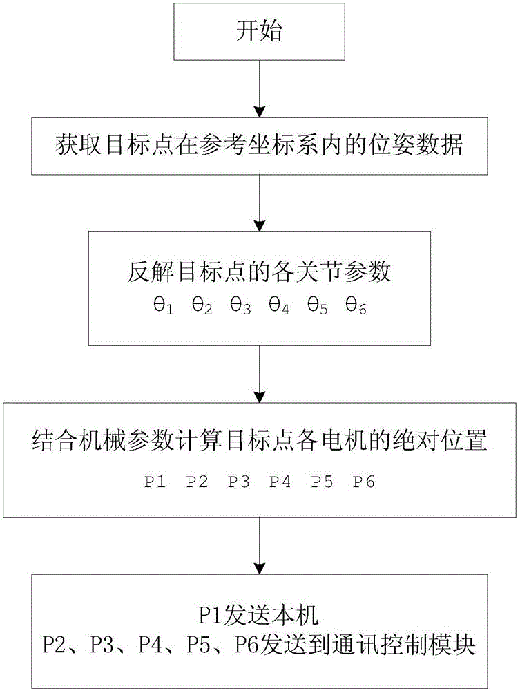
[0021] The invention discloses a distributed control system for a six-axis joint robot, which combines Figure 1 to Figure 5 As shown, it includes a six-axis articulated robot, a master station and five slave stations, and the master station and slave stations respectively correspond to six joints driving the six-axis articulated robot, wherein:

[0022] The master station is preset with a user program module, a PTP command execution module, a robot reverse solution calculation module, a communication control module, a virtual spindle module, an electronic cam module, and a motor control module. The user program module is used to execute the logic written by the user. Program, the logic program contains positioning instructions. When executing the positioning instructions, the PTP command execution module obtains the coordinates of the target poi...


PUM


Abstract

The invention discloses a six-axis joint robot distributed control system and a six-axis joint robot distributed control method. The control method includes the following steps that: a master station transmits a six-axis joint robot positioning instruction in a user program to a robot inverse solution calculation module; the robot inverse solution calculation module carries out inverse solution calculation on the position of a target point, analyzes the position of the target point to obtain corresponding parameters, and sends the parameters to the motor drivers of slave stations through a bus; after receiving valid data, the motor drivers obtain positioning operation parameters in the valid data through analysis, and send the positioning operation parameters to electronic cam modules; the electronic cam modules carry out periodic calculation under the driving of a virtual spindle and calculate periodic pulse quantity of each period; and motor control modules drive motor to operate according to the periodic pulse quantity. With the six-axis joint robot distributed control system and the six-axis joint robot distributed control method of the invention adopted, requirements for the calculation ability of the master station and requirements for the bandwidth of the bus can be lowered, and wiring and troubleshooting difficulty can be reduced, and anti-interference ability can be improved.

Description

technical field [0001] The invention relates to the technical field of robot control, in particular to a distributed control system and method for a six-axis joint robot. Background technique [0002] The six-axis articulated robot is a typical tandem industrial robot. It is one of the most common forms of industrial robots in the industrial field today. It is suitable for automated operations in many industrial fields, such as automatic assembly, automatic spraying, handling, coding Stacking, welding and other operations. The inverse solution of the six-axis joint robot refers to calculating the angle of each joint axis according to the given target pose and mechanical parameters, so that the movement of each joint motor can be controlled to reach the target pose. The calculation of the inverse solution is relatively complicated, so a dedicated controller is required to control the robot's action. At present, there are two mainstream technologies: [0003] 1. The solution...

Claims


Application Information

Patent Timeline
Patent Type & Authority Applications(China)
IPC IPC(8): G05B19/414
CPCG05B19/414
Inventor 陈阳高大林
Owner SHENZHEN VMMORE CONTROL TECH
Learn More