Methods for authenticating an identity of an article in electrical communication with a verifier system

Active Publication Date: 2006-10-05
LEXMARK INT INC
View PDF14 Cites 24 Cited by
  • Summary
  • Abstract
  • Description
  • Claims
  • Application Information

AI Technical Summary

Benefits of technology

[0010] The present invention relates to a method for authenticating a claimant having minimal computational power. Exemplary embodiments of the present invention provide for secure authentication while substantially lowering the computational power of the claimant, therefore allowing for many new applications for authentication (wherein previous authentication processes require substantially greater computational power). In one exemplary embodiment of the present invention, the only computational power required by the claimant is combinational logic. In other words, all that is required is AND, OR and similar logic instead of the multiplication operations typically required by current authentication methods. As such, the claimants might benefit from a much lower cost of electronics.
[0013] Exemplary methods of the present invention can be advantageous for providing claimant authentication to a verifier system while minimizing computational power required by the claimant. These and additional advantages will be apparent in view of the detailed description.

Problems solved by technology

The smart card itself is untrusted, thus with each commercial transaction it must be a claimant.
The secret key and the public key are mathematically dependent from each other, wherein the public key is easy to compute from the secret key, but the secret key is computationally unfeasible from the public key.
One drawback to both of these methods however is that substantial computational power typically must reside in the claimants.
While this computational power can be less than required by the verifier, it still requires a significant hurdle for a claimant which may be a simple mobile device.
This required computational power is cost prohibitive for many applications.

Method used


Image

  • Methods for authenticating an identity of an article in electrical communication with a verifier system
  • Methods for authenticating an identity of an article in electrical communication with a verifier system
  • Methods for authenticating an identity of an article in electrical communication with a verifier system

Examples


Embodiment Construction

[0017] Reference will now be made in detail to various embodiments which are illustrated in the accompanying drawings, wherein like numerals indicate similar elements throughout the views.

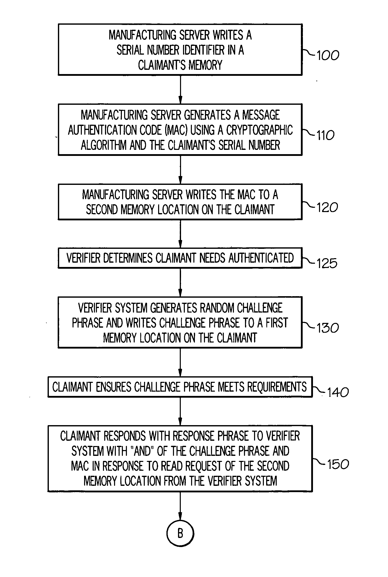
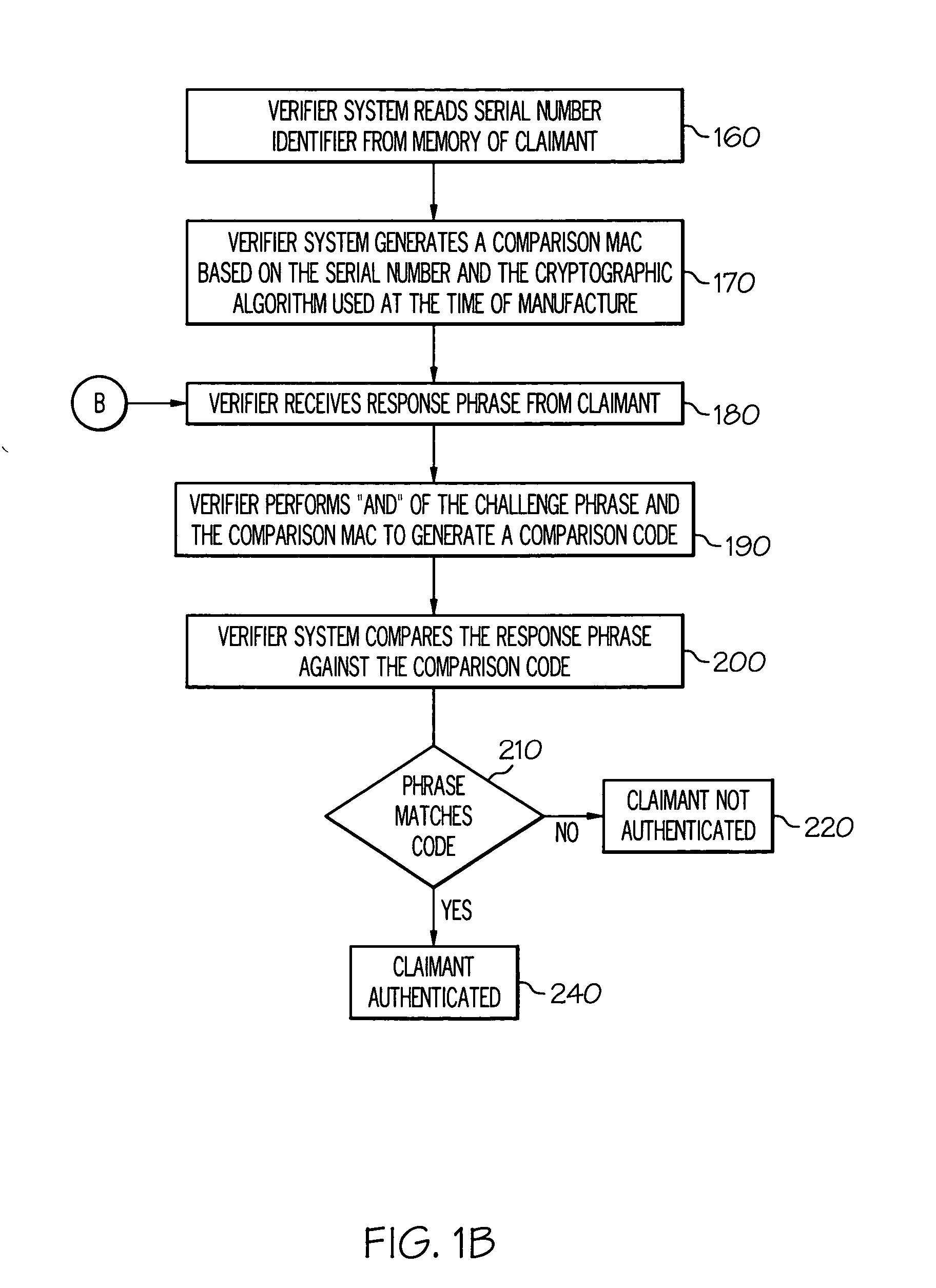
[0018] One embodiment of the present invention is a method for sending an authentication response from a claimant to a verifier system. The method comprises: storing a challenge phrase in a first memory location on the article, wherein the challenge phrase is received from the verifier system; retrieving a message authentication code (MAC) from a second memory location on the article, wherein the MAC is stored in the second memory location at the time of manufacturing of the article; sending a combinational logic gate output of the challenge phrase and the MAC in response to receiving a read request for the second memory location from the verifier system; retrieving a serial number identifier stored on the article, wherein the serial number identifier is stored on the article at the time of manufa...


PUM


Abstract

Methods for authenticating a property of an article in electrical communication with a verifier system including, for example, reading an identification code from the article, generating a challenge phrase from a verifier system, writing a challenge phrase to a first memory location on the article, reading a response phrase from the second memory location on the article, wherein the second memory location is configured to respond with a combinational logic gate output of the second memory location and the first memory location, generating a message authentication code by encrypting the identification code using a predetermined algorithm, generating a comparison code, wherein the comparison code is a combination logic gate output of the message authentication code and the challenge phrase, and determining if the comparison code is equivalent to the response phrase. Articles configured for use with the same.

Description

TECHNICAL FIELD [0001] This invention relates to methods for authenticating a claimant, wherein the authentication is implemented with minimal computational power utilized on the claimant. BACKGROUND OF THE INVENTION [0002] A field increasing in importance for many industries is the authentication of one component (e.g., the identity of the component) of an electrical system (the claimant) to another component of the system (the verifier). Authentication can be used for a number of different purposes, the specifics of which can be left to individual artisans. In one embodiment, authentication can be used to confirm to the verifier that a particular claimant is what it purports to be or is what the verifier expects it to be. Obviously, in an authentication process such as this, it can be desireable to trust the verifier. One typical means to ensure that the verifier is trusted is for the verifier to be hosted in a physically secure server or computer. The claimant is usually not trus...

Claims


Application Information

Patent Timeline
IPC IPC(8): H04L9/00
CPCH04L9/3271H04L2209/56H04L9/3242
Inventor ADKINS, CHRISTOPHER A.STRUNK, TIMOTHY L.
Owner LEXMARK INT INC
Why Eureka
Try Eureka