
Variable compression ratio engine

Inactive Publication Date: 2009-09-10
SYED AHMED +1
View PDF11 Cites 12 Cited by
  • Summary
  • Abstract
  • Description
  • Claims
  • Application Information

AI Technical Summary

Benefits of technology

[0016]Accordingly the present invention achieves the objectives with a simple, elegant solution having high functionality, reliability and long-term durability at low cost.
[0019]It is also an object of the invention to provide an engine capable of smoothly switching between different operating modes and fuels.
[0021]The variable clearance volume is determined by the positioning of a movable sub-piston mounted within a recessed cavity that opens upon the clearance space. The positioning of the sub-piston is effected by the rotational position of a setting cam that does away with the problematic hydraulics of earlier systems. The exemplary design features cams capable of being primed for forward movement of the volume regulating member during the neutral interval (exhaust-intake strokes), thereby minimizing the power requirement. In a further innovative step, a locking mechanism prevents the cams from backing up under the sudden rise of cylinder pressure. Stepless adjustment of the compression ratio is achieved over the entire load range. The design has the further advantage of having a very fast transient response in both directions.

Problems solved by technology

It is evident from the foregoing that current designs are seriously disadvantaged in terms of cost / complexity or capability.
Impractical design, low reliability and difficulty of manufacture are significant barriers eliminating them as serious contenders for production viable designs.

Method used


Image

  • Variable compression ratio engine
  • Variable compression ratio engine
  • Variable compression ratio engine

Examples


Embodiment Construction

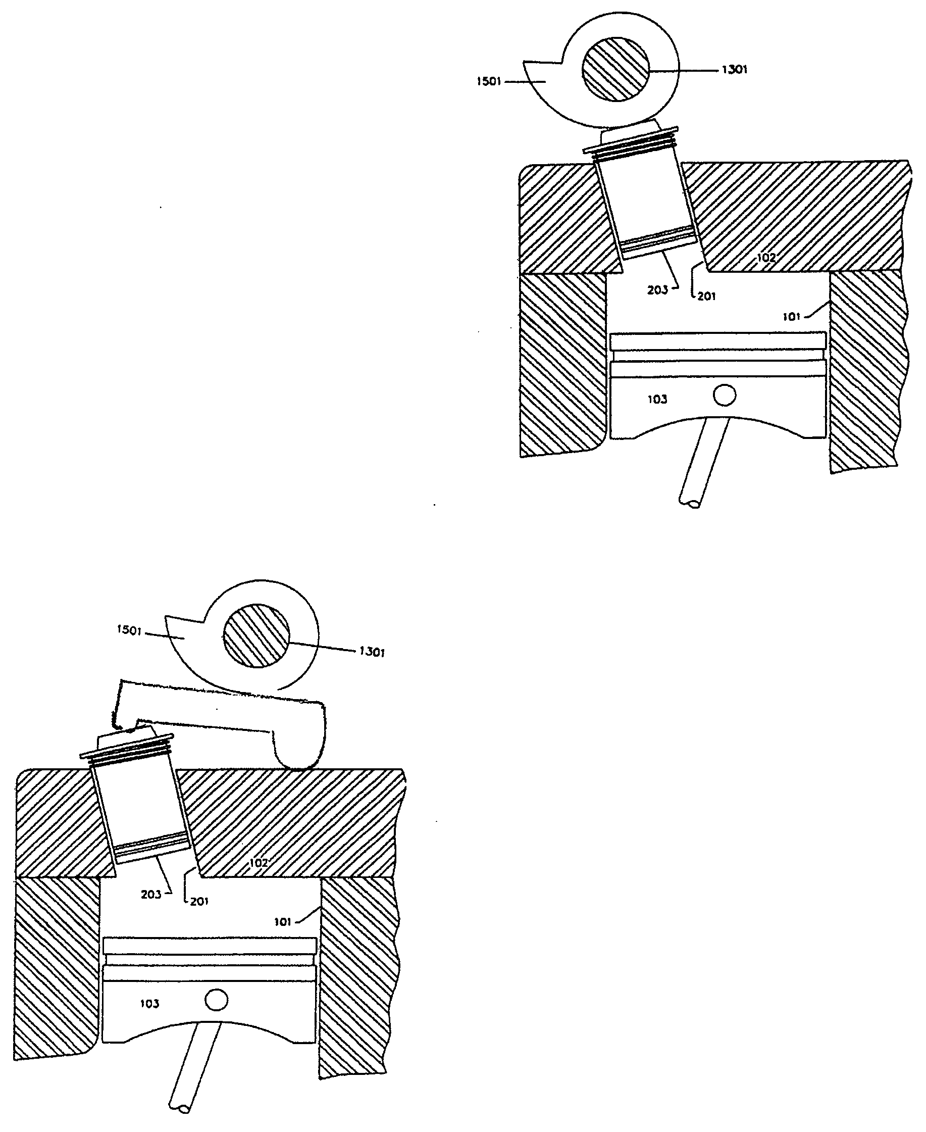
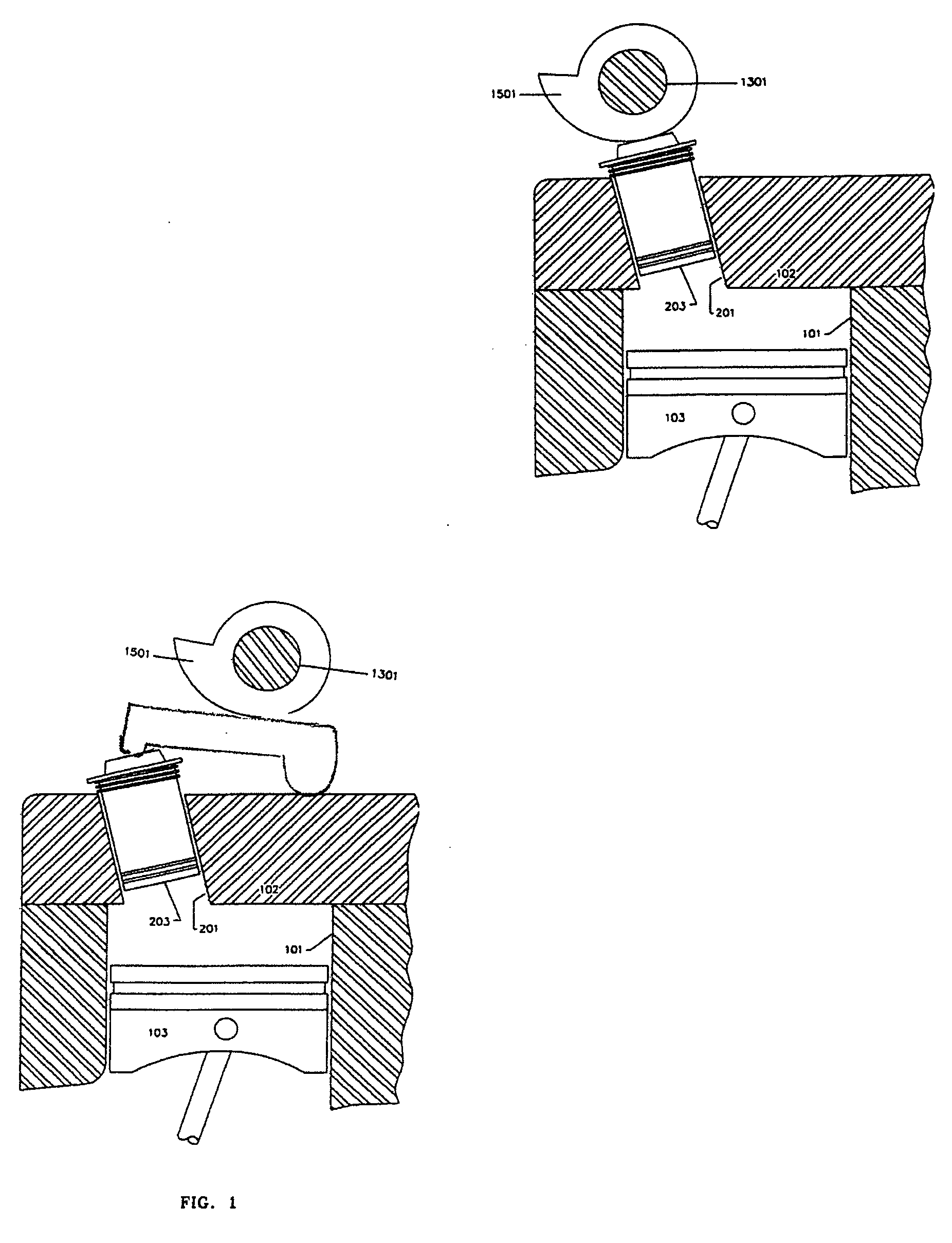
[0029]Referring now to the drawings, there is illustrated in FIG. 1 a sectional view of a cylinder in an internal combustion engine generally designated 10. The engine has a primary cylinder 101, a cylinder head 102, and a primary piston 103. A secondary cylinder 201 is formed in the cylinder head 102 and positioned so that the opening of the secondary cylinder 201 corresponds with a selected part of the volume which comprises the clearance volume at TDC. A secondary piston 203 is mounted within the secondary cylinder 201. The space below the piston 203 is added to the clearance volume in computing the compression ratio. As the secondary piston is lowered along the cylinder 201, the clearance volume is reduced and the compression ratio is increased. The opening of the secondary cylinder can be made as a narrow orifice.

[0030]In the embodiment shown in FIG. 1, the spark plug may be mounted within the secondary piston or elsewhere according to preference. The secondary piston will inco...


PUM


Abstract

A variable compression ratio mechanism for continuously varying the compression ratio of an internal combustion engine while minimizing the power requirement and providing internal clamping to isolate the setting mechanism from the reaction to combustion loads. The mechanism includes a setting cam (1501) actuated via an innovative torque storage system acting on an auxiliary piston (203) in the combustion chamber crown. The mechanism provides very fast and precise transient response without the use of hydraulic control. The invention desirably simplifies the control system and provides an elegant and compact solution for this purpose.

Description

CROSS-REFERENCE TO RELATED APPLICATIONS[0001]Not ApplicableFEDERALLY SPONSORED RESEARCH[0002]Not ApplicableSEQUENCE LISTING OF PROGRAM[0003]Not ApplicableFIELD OF THE INVENTION[0004]The invention relates to the field of internal combustion engines and in particular to engines whose compression ratio can be varied.BACKGROUND OF THE INVENTION[0005]Strict emissions standards coupled with requirements for improved fuel economy have mandated significant changes in the way automotive powertrains are designed. The primary disadvantages of the ICE arise from the fixed design points. Quantum improvements in ICE performance hinge on the successful implementation of adaptive engine geometry that is capable of dynamically optimizing key engine parameters throughout the load / speed range. Presently, design constraints are set by peak power conditions, but most driving takes place at part-load engine operation. This allows for the possibility of significantly improving overall efficiency and driva...

Claims


Application Information

Patent Timeline
IPC IPC(8): F02B75/04F02D15/04
CPCF02B75/042
Inventor SYED, AHMEDDAR, ATHER RASHID
Owner SYED AHMED
Learn More