Diopter self-adaptive head-mounted display device
A head-mounted display and adaptive technology, applied in optics, optical components, instruments, etc., can solve the wearer's eye fatigue and affect the visual experience of the device, and achieve the effects of avoiding visual fatigue, protecting eyes, and compact size
- Summary
- Abstract
- Description
- Claims
- Application Information
AI Technical Summary
Problems solved by technology
Method used
Image
Examples
Embodiment 1
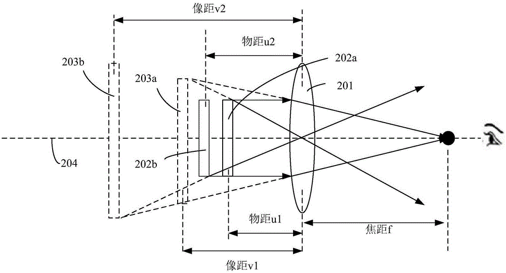
[0047] Figure 4 schematically shows an embodiment of the diopter adaptive head-mounted display device according to the present invention: the relative movement of the display screen and the optical lens 401 is set so that the optical lens 401 is fixed, and the display screen is on the optical axis 404 direction, so that the adjusted object distance u2, image distance v3 and focal length f satisfy the first condition 1 / f=1 / u2−1 / v3.
[0048] As shown in Figure 4(a), the current image 402 in the display screen has an object distance u1, the optical lens shown has a focal length f, and the current virtual image 403a presented by the current image 402 through the optical lens 401 and converged in the eye has an image distance v1, The virtual image 403b of the image at the previous moment has an image distance v2. In order to prevent the viewer from actively adjusting the line of sight direction of the eyes and the focal length of the eye lens to cause fatigue, the present invention ...
Embodiment 2
[0051] Figure 5 schematically shows an embodiment of the diopter adaptive head-mounted display device according to the present invention: the relative movement of the display screen and the optical lens 501 is also set to fix the optical lens 501, and the display screen is on the optical axis Move in direction 504 so that the adjusted object distance u2, image distance v3 and focal length f satisfy the first condition 1 / f=1 / u2−1 / v3.
[0052] As shown in Figure 5(a), the current image 502 in the display screen has an object distance u1, the optical lens shown has a focal length f, and the current virtual image 503a presented by the current image 502 through the optical lens 501 has an image distance v1. The virtual image 503b of the image at the previous moment has an image distance v2. In order to avoid fatigue caused by the viewer actively adjusting the line of sight direction of the eyes and the focal length of the eye lens, the present invention adjusts the position of the d...
Embodiment 3
[0055] Figure 6 schematically shows an embodiment of the diopter adaptive head-mounted display device according to the present invention: the relative movement of the display screen and the optical lens 601 is also set to the direction of the optical axis 604 between the display screen and the optical lens Both of them move in cooperation with each other, so that the adjusted object distance u2, image distance v3 and focal length f satisfy the first condition 1 / f=1 / u2−1 / v3.
[0056] As shown in Figure 6(a), the current image 602 in the display screen has an object distance u1, the optical lens 601 shown has a focal length f, and the current virtual image 603a presented by the current image 602 through the optical lens 601 has an image distance v1 , the virtual image 603b of the image at the previous moment has an image distance v2. In order to prevent the viewer from actively adjusting the line of sight direction of the eyes and the focal length of the eye lens to cause fatigue...
PUM
 Abstract
Description
Claims
Application Information
 - R&D
- Intellectual Property
- Life Sciences
- Materials
- Tech Scout
- Unparalleled Data Quality
- Higher Quality Content
- 60% Fewer Hallucinations
Browse by: Latest US Patents, China's latest patents, Technical Efficacy Thesaurus, Application Domain, Technology Topic, Popular Technical Reports.
© 2025 PatSnap. All rights reserved.Legal|Privacy policy|Modern Slavery Act Transparency Statement|Sitemap|About US| Contact US: help@patsnap.com


