
A poly wave turbine power generation device

A power generation device and turbine-type technology, applied in safety devices, hydroelectric power generation, ocean energy power generation, etc., can solve the problems of high device cost, difficult development, poor ability to absorb wave energy, etc., and achieve convenient movement and good power generation efficiency , Strong anti-corrosion effect

Active Publication Date: 2019-01-22
WUHAN UNIV OF TECH
View PDF6 Cites 0 Cited by
  • Summary
  • Abstract
  • Description
  • Claims
  • Application Information

AI Technical Summary

Problems solved by technology

The advantage of the raft type ocean energy power generation technology is that there is only angular displacement between the raft bodies, even under high waves, the displacement will not be too large, so the anti-wind and wave performance is better, and it has better energy transfer efficiency and good power generation stability The disadvantage is that the device is arranged in the direction of the wave, and the ability of the raft wave energy generator to absorb wave energy is relatively poor. The amount of material per unit power is larger than that of the device arranged in the vertical wave direction, resulting in higher device cost; and mooring is more difficult
[0007] 4. The existing offshore platforms mainly transmit power through submarine cables, and submarine cables are a project that is difficult to develop, requires a lot of investment, frequent accidents, and high maintenance costs
[0008] Most of the devices or power supply platforms at the present stage use offshore solar energy and wind energy, but few use ocean wave energy power generation technology. Moreover, at this stage, floating ocean wave energy conversion devices also have the problems of electric energy storage and power transmission to the shore. However, this technical obstacle can also be ignored if it is dedicated to supplying power to offshore platforms.

Method used


Image

  • A poly wave turbine power generation device
  • A poly wave turbine power generation device
  • A poly wave turbine power generation device

Examples


Embodiment Construction

[0028] The present invention will be further described below in conjunction with the accompanying drawings.

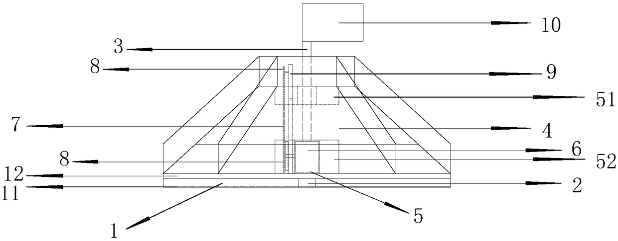
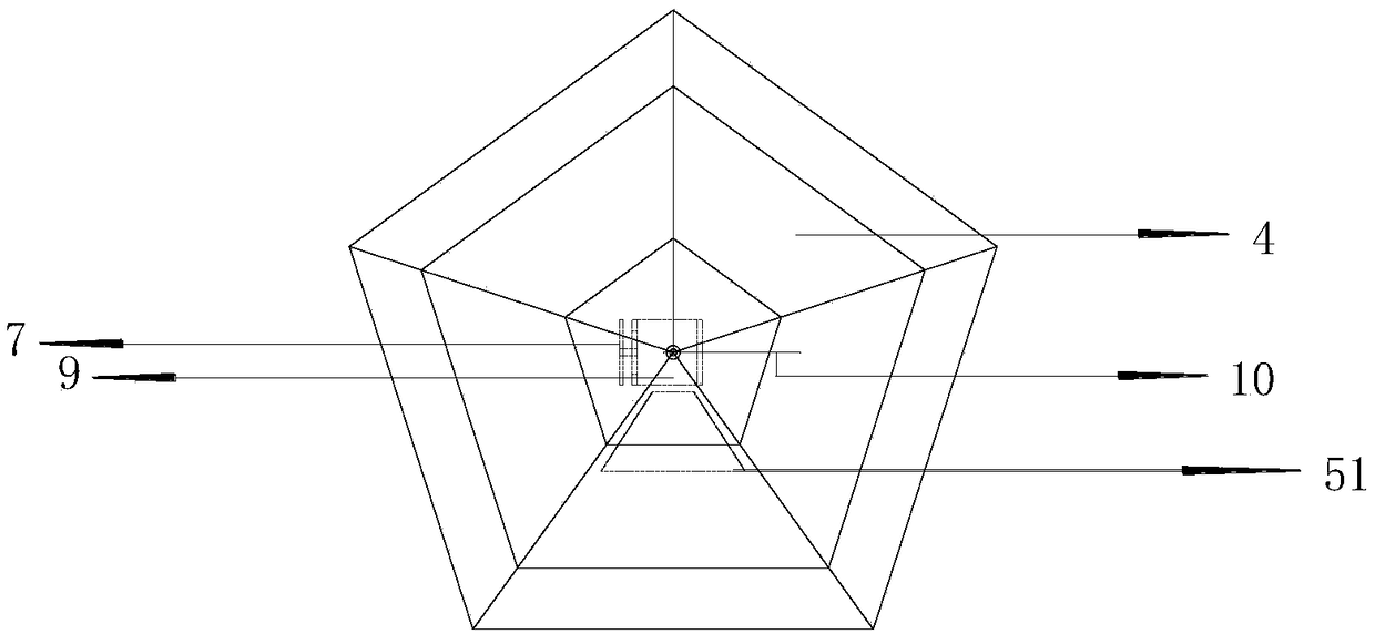
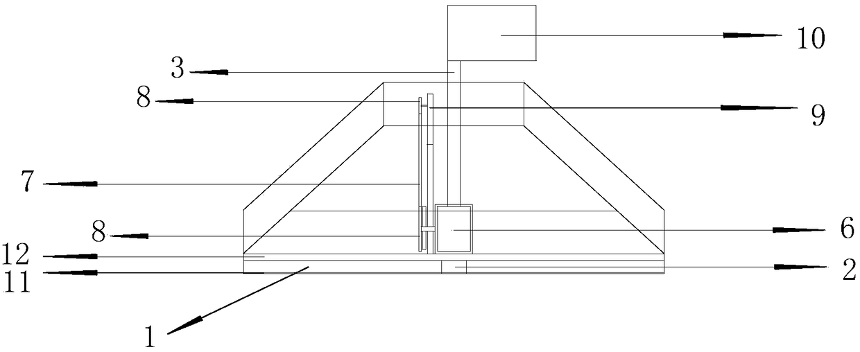
[0029] see Figure 1-Figure 4 , a poly wave turbine type power generation device, comprising a bottom support plate 1, the bottom support plate is composed of an upper plate frame 12 and a lower plate frame 11 connected by a bottom bearing seat 2, the upper plate frame and the lower plate frame are relatively fixed, and the bottom bearing The seat 2 passes through the upper and lower plate frames and is fixed thereto. The wave-forming box 5 is connected to the bearing used in conjunction with the bottom bearing seat 2 at the center of the bottom support plate, and the wave-forming box can rotate together with the bearing; The surface is provided with a retractable pillar 3;

[0030] The wave-gathering turbine power generation device also includes five identical wave guide plates 4 on the periphery. The width of the wave guide plates narrows from bottom to top and is i...


PUM


Abstract

The invention provides a wave-focusing turbine type power generating device, which comprises a bottom support plate and wave guiding plates on the periphery. A wave focusing box is connected onto a bearing matched with a bearing seat in the center of the bottom support plate, and can be rotated together with the bearing; a telescoping prop is arranged on the upper surface of the wave focusing box; each wave guiding plate narrows down from bottom to top, and is arranged at an inclined angle; a gap is formed between the bottom part of each wave guiding plate and an upper grillage of the bottom support plate; a turbine is arranged in the wave focusing box; a belt is connected onto the turbine; the turbine rotates to drive a belt pulley to rotate; the belt pulley is connected with a power generator; the power generator is arranged on the upper part of the prop; a windward plate is arranged on the top part of the prop. The wave-focusing turbine type power generating device provided by the invention directly adopts wave energy-mechanical energy-electric energy, and not only utilizes wave potential energy, but also utilizes wave kinetic energy, so that the power generating efficiency is better.

Description

technical field [0001] The invention relates to a power generation device, in particular to a wave gathering turbine type power generation device, which belongs to the technical field of wave power generation. Background technique [0002] my country's industrial development is very dependent on fossil energy, and the crisis of fossil energy has become increasingly prominent and the ecological environment has also been seriously damaged. Therefore, it is imminent to develop new energy and reduce dependence on fossil energy. Ocean energy accounts for about 70% of the world's energy. In this regard, our country is only in its infancy, and various experimental tidal power stations have been developed in some coastal areas, which has laid a preliminary foundation for the further development and utilization of marine energy. Due to the harsh operating environment of marine wave energy power generation systems, compared with other renewable energy power generation systems such as...

Claims


Application Information

Patent Timeline
Patent Type & Authority Patents(China)
IPC IPC(8): F03B13/14F03B13/22F03B15/00F03B11/00
CPCF03B11/00F03B13/14F03B13/22F03B15/00Y02E10/20Y02E10/30
Inventor 吴静萍吴昊吴沼涛龚恒翰
Owner WUHAN UNIV OF TECH
Learn More