Water circulation system for vacuum setting machine

A technology of setting machine and water circulation, applied in the field of water circulation system and water circulation system of vacuum setting machine, can solve the problems that pipes cannot be cooled in a comprehensive and timely manner, cannot quickly form a circulating water circuit, and the time of a single water circulation is long, etc. Cost control, prevention of high water temperature, and short cycle time

Inactive Publication Date: 2016-09-07
NINGBO FANGLI TECH
View PDF6 Cites 4 Cited by
  • Summary
  • Abstract
  • Description
  • Claims
  • Application Information

AI Technical Summary

Problems solved by technology

[0003] In the existing sizing machine, a nozzle is generally installed in the body of the sizing machine, and a water source is installed outside the box. The water source and the nozzle are connected through a water inlet pipe, and the bottom of the box communicates with the outside. Cool down the high-temperature pipes in the box, and the cooling water will heat up into high-temperature water and flow out from the bottom of the box. Due to the large temperature difference between the water flowing into and out of the shaping machine, it is impossible to quickly form a circulating water circuit. The traditional solution is Continuously drain high-temperature water and continuously supply a large amount of cooling water, and then cool the received high-temperature water into cooling water through the cooling device and put it into use again, thus forming an indirect circulating waterway, but this method has the following technical problems: 1. Serious Waste of water resources, high energy consumption, and high cost of use; 2. This indirect circulating waterway takes a long time for a single water cycle, and the water cooling efficiency is low, resulting in the inability of the pipe to be fully and timely cooled

Method used


Image

  • Water circulation system for vacuum setting machine
  • Water circulation system for vacuum setting machine
  • Water circulation system for vacuum setting machine

Examples


Embodiment Construction

[0055] The following are specific embodiments of the present invention and in conjunction with the accompanying drawings, the technical solutions of the present invention are further described, but the present invention is not limited to these embodiments.

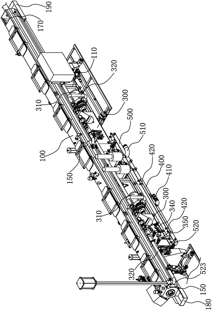
[0056] Such as Figure 1 to Figure 3 As shown, the present invention is used in the water circulation system of the vacuum setting machine, which is a part of the vacuum setting machine. The water circulation system includes a box body 100, a spray assembly, a water supply assembly, a water inlet assembly and a drainage assembly.

[0057] The box body 100 extends in the axial direction, and the inside of the box body 100 is axially penetrated to form an accommodating cavity for pipes to pass through. The box body 100 has a feed end and a discharge end.

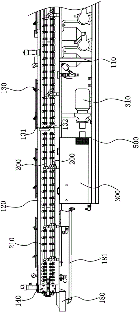
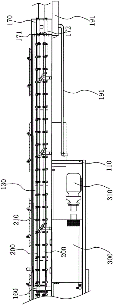
[0058] Such as Figure 2 to Figure 4As shown, the shower assembly includes a shower pipe 200 and a shower head 210 .

[0059] There are two groups of spray pipes 200 dis...


PUM


Abstract

The invention provides a water circulation system for a vacuum setting machine and belongs to the technical field of pipe setting equipment. The technical problems of existing setting machines are low in water circulation efficiency, large in energy consumption and poor in pipe cooling effect are solved. The water circulation system for the vacuum setting machine comprises a box, a spraying assembly, a water supply assembly, a water feeding assembly and a water draining assembly, wherein the water feeding assembly communicates with the water supply assembly and feeds water to the water supply assembly for centralization; the water feeding assembly feeds water to the water supply assembly, and the water circulates among the water supply assembly, the spraying assembly and the box; when the water temperature of the water supply assembly reaches a preset value, part of water can be discharged through the water draining assembly; when the water temperature of the water supply assembly reaches the preset temperature value, part of high-temperature water is discharged through the water draining assembly, and cooling water feeding and high-temperature water draining are carried out simultaneously, so that the pipe cooling effect is good, water resources are effectively saved, energy consumption is small, and the use cost is controlled.

Description

technical field [0001] The invention belongs to the technical field of pipe shaping equipment, and relates to a water circulation system, in particular to a water circulation system for a vacuum shaping machine. Background technique [0002] The vacuum setting machine is a special equipment for cooling and shaping the pipe. Its purpose is to provide a vacuum environment for the formed high-temperature pipe, and cool down and shape the pipe in the vacuum environment to make the pipe into a fixed shape. [0003] In the existing sizing machine, a nozzle is generally installed in the body of the sizing machine, and a water source is installed outside the box. The water source and the nozzle are connected through a water inlet pipe, and the bottom of the box communicates with the outside. Cool down the high-temperature pipes in the box, and the cooling water will heat up into high-temperature water and flow out from the bottom of the box. Due to the large temperature difference b...

Claims


Application Information

Patent Timeline
IPC IPC(8): B29C47/90B29L23/00B29C48/90
CPCB29C48/901B29C48/905B29C2791/006B29L2023/00
Inventor 林晓东王福春
Owner NINGBO FANGLI TECH
Why Eureka
Try Eureka