A shell and tube condenser

A condenser and shell-and-tube technology, which is applied in the field of shell-and-tube condensers for air source heat pump devices, can solve the problems of bulky condensers and achieve the effects of improving heat exchange efficiency, large heat exchange area, and reducing loss

Active Publication Date: 2018-07-06
SUZHOU HOTFROM HEAT PUMP EQUIP TECH CO LTD
View PDF9 Cites 0 Cited by
  • Summary
  • Abstract
  • Description
  • Claims
  • Application Information

AI Technical Summary

Problems solved by technology

But for a general condenser, if the path of heat exchange is too long, it will lead to a large volume of the entire condenser

Method used


Image

  • A shell and tube condenser
  • A shell and tube condenser
  • A shell and tube condenser

Examples


Embodiment Construction

[0024] The present invention will be further described below in conjunction with specific embodiments and accompanying drawings.

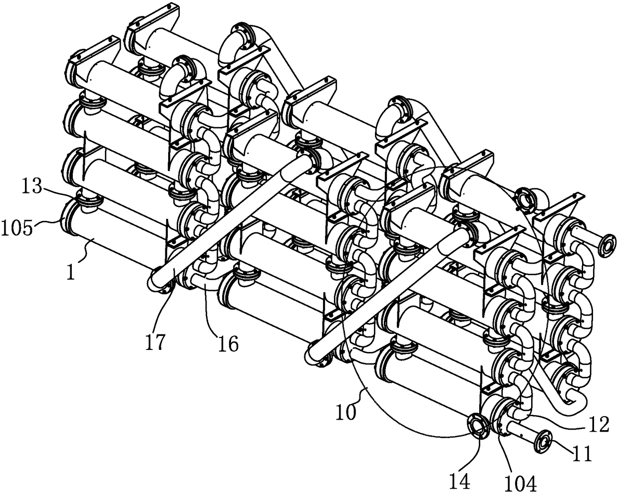
[0025] See Figure 1-4 As shown, the present invention is a shell-and-tube condenser, which is composed of a plurality of condenser units 1 connected in series,

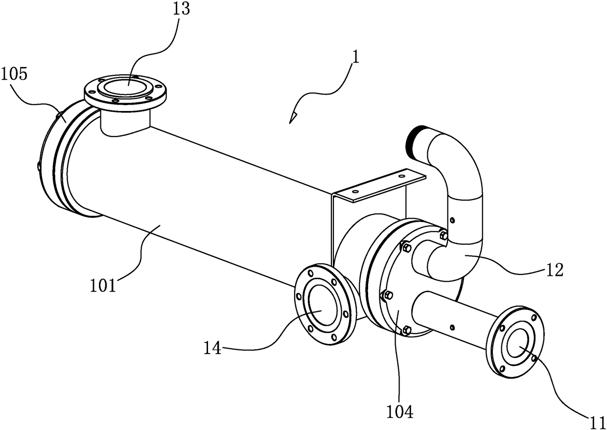
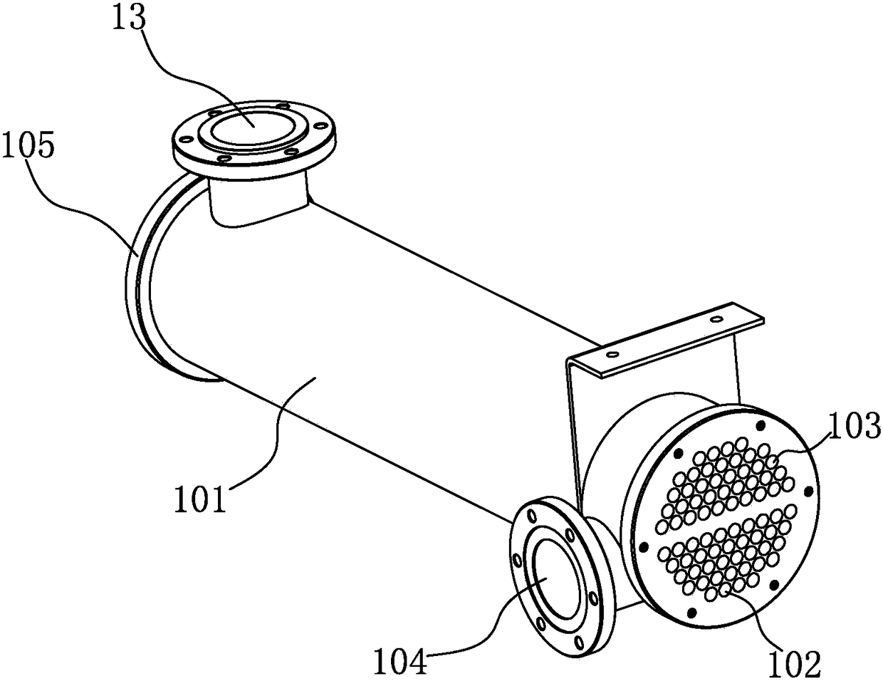
[0026] see Figure 2-4 As shown, the condenser unit 1 has a water inlet 11, a water outlet 12, a refrigerant inlet 13 and a refrigerant outlet 14, and a mutually isolated tube-side channel and a shell-side channel are formed in each condenser unit 1. The tube-side channel communicates with the water inlet 11 and the water outlet 12; the shell-side channel communicates with the refrigerant inlet 13 and the refrigerant outlet 14. The specific structure of the condenser unit is as follows: the condenser unit 1 includes: a tubular housing 101, a plurality of water inlet pipes 102 and outlet pipes located in the tubular housing 101 are arranged between the front and rear end faces of the tub...


PUM


Abstract

The invention discloses a shell-and-tube condenser for air source heat pump units. The shell-and-tube condenser is composed of multiple condenser units connected in series. A tube pass channel and a shell pass channel isolated from each other are formed in each condenser unit, wherein the tube pass channel is communicated with a water inlet and a water outlet, and the shell pass channel is communicated with a refrigerant inlet and a refrigerant outlet. With the order of water flow as a reference, among the multiple condenser units connected in series, the water outlet of the first condenser unit is communicated with the water inlets of the subsequent condenser units through a pipeline, low-temperature water flows into the water inlet of the first condenser unit, and is heated gradually into hot water, and the hot water flows out of the water outlet of the last condenser unit. The condenser is composed of multiple condenser units which are distributed in whole columns, so that enough condenser units can be installed in a limited space, a long enough heat transfer path is obtained, and the efficiency of heat exchange is improved.

Description

Technical field: [0001] The invention relates to the technical field of heat pump products, in particular to a shell-and-tube condenser for an air source heat pump device. Background technique: [0002] The working principle of the heat pump system is the same as that of the refrigeration system. The refrigeration system (compression refrigeration) generally consists of four parts: compressor, condenser, throttle valve, and evaporator. Its working process is: low-temperature and low-pressure liquid refrigerant (such as Freon), first absorbs heat from a high-temperature heat source (such as normal temperature air) in an evaporator (such as an air-conditioning indoor unit) and vaporizes into low-pressure steam. Then the refrigerant gas is compressed into high-temperature and high-pressure vapor in the compressor, and the high-temperature and high-pressure gas is cooled and condensed into high-pressure liquid by a low-temperature heat source (such as cooling water) in the cond...

Claims


Application Information

Patent Timeline
Patent Type & Authority Patents(China)
IPC IPC(8): F25B39/04
CPCF25B39/04F25B2339/04
Inventor 郑剑泽李昌
Owner SUZHOU HOTFROM HEAT PUMP EQUIP TECH CO LTD
Why Eureka
Try Eureka