Forced idling lubrication system of hydraulic retarder

A hydraulic retarder and forced lubrication technology, which is applied in the direction of liquid resistance brakes, lubricating parts, engine lubrication, etc., can solve the problems of complex hydraulic oil circuit system, high manufacturing precision and cost, and large installation size, etc., to achieve High safety and reliability, convenient use and maintenance, and stable pressure

Inactive Publication Date: 2016-08-31
SHAANXI FAST GEAR CO
View PDF8 Cites 2 Cited by
  • Summary
  • Abstract
  • Description
  • Claims
  • Application Information

AI Technical Summary

Problems solved by technology

Although the lubricating effect is better, the traditional hydraulic pump has complex structure, large installation size, high manufacturing precision and cost, and the matching hydraulic oil circuit system is also relatively complicated.

Method used


Image

  • Forced idling lubrication system of hydraulic retarder
  • Forced idling lubrication system of hydraulic retarder

Examples


Embodiment Construction

[0018] The present invention will be further described in detail below in conjunction with specific embodiments, which are explanations of the present invention rather than limitations.

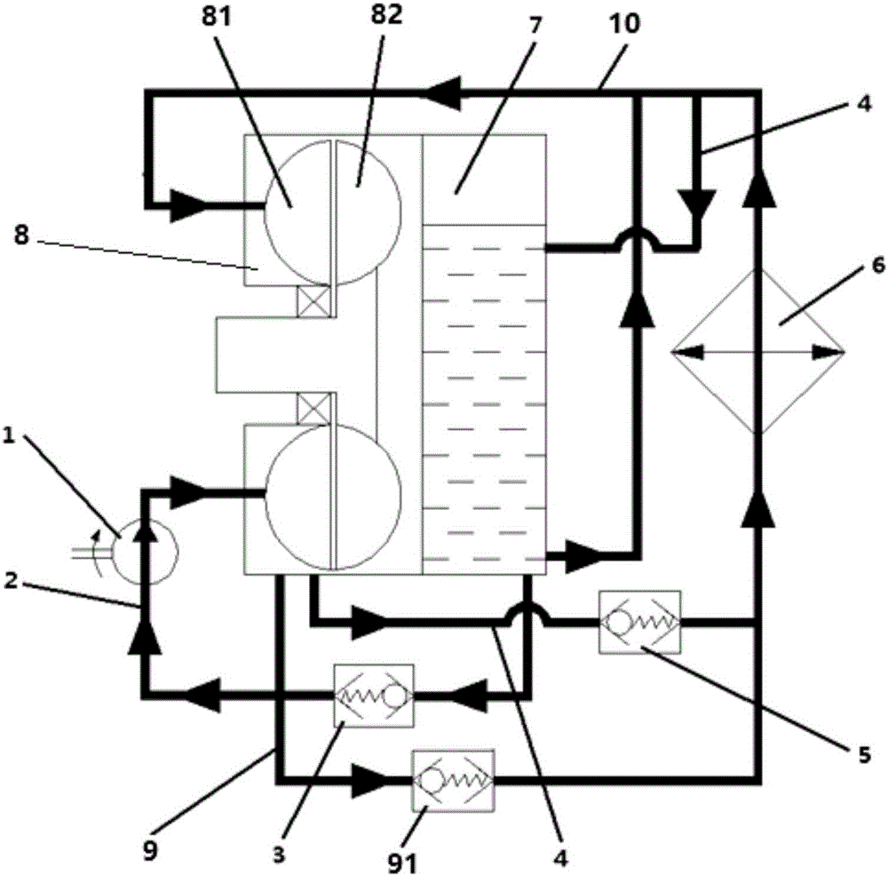
[0019] The present invention adopts a novel threaded pump as the hydraulic retarder idling lubrication system of the oil pumping element, such as figure 1 As shown, it consists of a threaded pump 1, a lubricating circulation oil inlet passage 2, a lubricating circulation oil inlet check valve 3, a lubricating circulation oil outlet passage 4, a lubricating circulation oil outlet check valve 5, a heat exchanger 6 and The oil pool consists of 7. The retarder 8 is provided with a working cycle oil outlet circuit 9 and a working cycle oil inlet circuit 10; when working, the oil enters the heat exchanger 6 from the retarder 8 through the working cycle oil outlet check valve 91 Flow into the oil pool 7 or directly into the working cycle oil inlet 10, so that the cooled oil enters the retarder 8 fo...


PUM


Abstract

The invention discloses a forced idling lubrication system of a hydraulic retarder. According to the forced idling lubrication system of the hydraulic retarder, the manufacturing difficulty is low, and oil for idling lubrication can be cooled. The forced idling lubrication system comprises an oil pond, a lubrication circulated oil outlet path with the output end connected to the oil pond, and a lubrication circulated oil inlet path with the input end connected to the oil pond. The input end of the lubrication circulated oil outlet path is connected to the hydraulic retarder and communicates with a working cavity. A heat exchanger is arranged on the lubrication circulated oil outlet path. The output end of the lubrication circulated oil inlet path is connected to the hydraulic retarder and communicates with a working cavity. A thread pump is arranged on the lubrication circulated oil inlet path and linked with a rotor of the hydraulic retarder. Through the lubrication circulated oil inlet path and the lubrication circulated oil outlet path, forced lubrication for the retarder is achieved; and by arranging the thread pump linked with the rotor of the retarder on the oil inlet path, the effect that as long as the rotor of the retarder rotates, the thread pump cannot stop operating and the oil inlet path where the thread pump is arranged can operate normally is achieved, and normal lubrication is ensured when the hydraulic retarder is in the idling state.

Description

technical field [0001] The invention relates to a lubricating system of a buffer, in particular to an idling forced lubricating system of a hydraulic retarder. Background technique [0002] Since the retarder is equipped with a heat exchanger for cooling the oil, the oil resistance is large, and the oil circulation is not smooth when the retarder is idling, which may easily cause poor lubrication of the internal components of the retarder. At present, in the field of hydraulic retarder, the following solutions are mainly adopted to solve the lubrication problem of internal components when the retarder is idling: 1. Set up a special idling lubricating oil channel to reduce oil resistance. 2. Add a hydraulic control valve to control the oil flow direction when the retarder is idling, so that the oil flows to the parts that need to be lubricated without passing through the heat exchanger. 3. Add a forced lubricating oil pump. When the retarder is idling, the oil pump sucks a s...

Claims


Application Information

Patent Timeline
Patent Type & Authority Applications(China)
IPC IPC(8): F16N7/40F16D57/00F16N39/02F04D3/02
CPCF16N7/40F04D3/02F16D57/00F16N39/02F16N2270/70
Inventor 孙博王伟健高帅陈俊宇
Owner SHAANXI FAST GEAR CO
Why Eureka
Try Eureka