Eureka AIR delivers breakthrough ideas for toughest innovation challenges, trusted by R&D personnel around the world.

A silent controllable electric pinch valve

A pinch valve, electric technology, applied in the direction of diaphragm valve, valve device, valve details, etc., can solve the problems of large starting current of electromagnet, short electromagnet stroke, unfavorable recovery of patients, etc., and achieve the effect of controlling fluid flow rate

Active Publication Date: 2018-03-06
NANJING UNIV OF SCI & TECH
View PDF7 Cites 0 Cited by
  • Summary
  • Abstract
  • Description
  • Claims
  • Application Information

AI Technical Summary

Problems solved by technology

However, the electromagnetic pinch valve has the following defects: (1) When the electromagnet pulls in and releases, it will produce a "popping" sound, which cannot meet the quiet requirements of the hospital ward; (2) The electromagnet only has pull-in and release. In two states of opening, the pinch valve cannot control the flow rate of the fluid in the pipe; (3) The starting current of the electromagnet is very large; (4) The stroke of the electromagnet is short, resulting in a short stroke of the pinch valve
[0004] Especially when electric pinch valves are used in the medical field, the sound from the electromagnet is likely to make the patient feel irritable, which is not conducive to the recovery of the patient.

Method used


Image

  • A silent controllable electric pinch valve

Examples


Embodiment Construction

[0018] The present invention will be further described below in conjunction with the accompanying drawings and specific embodiments.

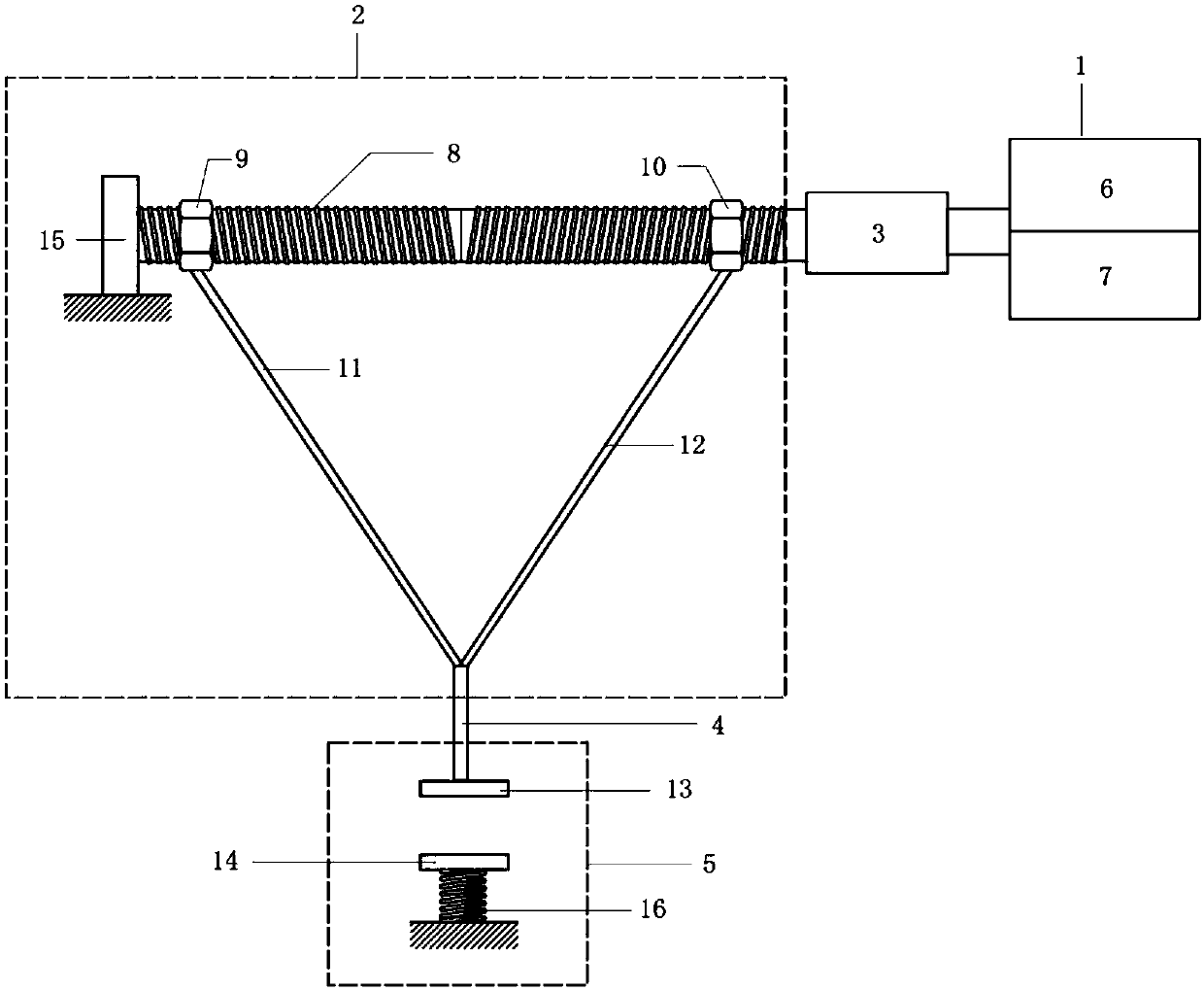
[0019] figure 1 It is a schematic structural diagram of components inside the electric pinch valve housing, including: a control component 1, a motion conversion component 2, a stepping motor 3, a connecting rod 4, and a pinch head component 5.

[0020] Wherein the control assembly 1 includes a single-chip microcomputer 6 (including an auxiliary circuit) and a driving circuit 7, the single-chip microcomputer controls the speed and the number of rotations of the stepping motor, and the driving circuit provides suitable voltage and current for the stepping motor.

[0021] The motion conversion assembly 2 includes a screw mandrel 8, nuts (9 and 10) and connecting arms (11 and 12); the screw mandrel 8 takes the midpoint as a symmetrical point, the threads on both sides are opposite, and a nut is respectively arranged on both sides of the screw mand...


PUM


Abstract

The invention discloses a mute controllable electric pinch valve. The mute controllable electric pinch valve comprises a valve shell as well as a control assembly, a motion transformation assembly, a step motor, a connecting rod and a pinch head assembly which are arranged in the valve shell, wherein the pinch head assembly comprises an upper valve plate and a lower valve plate; a hose passage is arranged between the upper valve plate and the lower valve plate; under the control of the control assembly, the step motor drives the motion transformation assembly for transforming rotation motion of the step motor into linear motion; the motion transformation assembly is connected with the upper valve plate through the connecting rod; and the upper valve plate and the lower valve plate are clamped or a hose is loosened by virtue of the linear motion of the upper valve plate. The mute controllable electric pinch valve disclosed by the invention solves the problems that an electromagnetic pinch valve is great in noise, is non-adjustable, is great in starting current, is short in stroke and the like, and meets the special use requirements of a hospital ward. The mute controllable electric pinch valve also solves the problem that the electromagnetic pinch valve cannot adjust closing degree of the pinch head, so that the effect of controlling fluid velocity is achieved by controlling a distance between valve plates.

Description

technical field [0001] The invention belongs to the field of electric valves, in particular to a silent controllable electric pinch valve. Background technique [0002] Pinch valve, also known as pinch valve, air bag valve, pinch off valve, etc. in China, is now used in many fields such as sewage treatment, power plant, mining, chemical industry, and medical treatment. According to different driving methods, pinch valves can be divided into manual pinch valves, pneumatic pinch valves, electric pinch valves and hydraulic pinch valves. [0003] Most of the currently used electric pinch valves are driven by electromagnets. Since this type of pinch valve can be made into a microstructure, it is widely used in the medical field. However, the electromagnetic pinch valve has the following defects: (1) When the electromagnet pulls in and releases, it will produce a "popping" sound, which cannot meet the quiet requirements of the hospital ward; (2) The electromagnet only has pull-in...

Claims


Application Information

Patent Timeline
Patent Type & Authority Patents(China)
IPC IPC(8): F16K7/06F16K31/04
CPCF16K7/06F16K31/04
Inventor 窦磊
Owner NANJING UNIV OF SCI & TECH
Why Eureka
Eureka Blog
Learn More