
Pressure relief type shock absorber for drill stems

A shock absorber and pressure relief technology, used in drill pipes, drill pipes, drilling equipment, etc., can solve the problems of fatigue damage of drilling tools and drill bits, discount of shock absorption effect, economic losses, etc., and achieve simple structure, processing and assembly. Convenience and the effect of reducing drilling costs

Active Publication Date: 2016-08-31
INST OF SINOPEC OILFIELD EQUIP CORP +1
View PDF6 Cites 6 Cited by
  • Summary
  • Abstract
  • Description
  • Claims
  • Application Information

AI Technical Summary

Problems solved by technology

However, they all still have a shortcoming: when the vibration impact force of the drill string is greater than the limit of the shock absorption force that the damping structure of the shock absorber can absorb, the remaining impact force will still act on the drill tool and the drill bit after being partially absorbed by the shock absorber unit. At this time, the shock absorber cannot completely convert the rigid vibration of the drill string into flexible vibration, which obviously shows "failure" or "partial failure", which leads to fatigue damage of drill tools and bits, and eventually brings certain economic losses
The current solution to this problem is to increase the damping coefficient of the shock absorber, but increasing the damping coefficient will inevitably bring new problems. When the damping coefficient is too large, the shock absorber is similar to a rigid drill string, and its shock absorption effect is great. Discounted, it still fails to achieve the purpose of converting rigid vibration into flexible vibration

Method used


Image

  • Pressure relief type shock absorber for drill stems
  • Pressure relief type shock absorber for drill stems
  • Pressure relief type shock absorber for drill stems

Examples


Embodiment Construction

[0030] The present invention will be further described in detail below in conjunction with the accompanying drawings, so that those skilled in the art can implement it with reference to the description.

[0031] It should be understood that terms such as "having", "comprising" and "including" as used herein do not entail the presence or addition of one or more other elements or combinations thereof.

[0032]It should be noted that the experimental methods described in the following embodiments, unless otherwise specified, are conventional methods, and the reagents and materials, if not otherwise specified, can be obtained from commercial sources; in the description of the present invention, The terms "landscape", "portrait", "top", "bottom", "front", "rear", "left", "right", "vertical", "horizontal", "top", "bottom", The orientation or positional relationship indicated by "inner", "outer", etc. is based on the orientation or positional relationship shown in the drawings, which...


PUM


Abstract

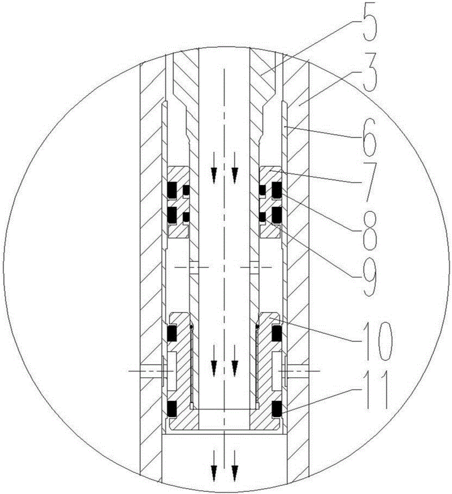
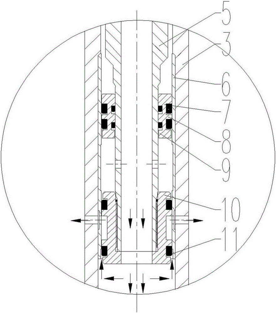
The invention discloses a pressure relief type shock absorber for drill stems. The pressure relief type shock absorber for the drill stems comprises a shock absorption unit and a pressure relief unit. The pressure relief unit comprises a cylinder sleeve and a pressure relief piston. The cylinder sleeve is arranged on the inner wall of a connection barrel coaxially to form a first sealing plane. The upper portion and the lower portion of the periphery of the pressure relief piston are concave in the radial direction to form a first groove, the middle of the periphery of the pressure relief piston is concave inwards to form a second groove, and a first sealing piece is arranged in the first groove annularly. At least one first pressure relief hole is formed in the portion, between a shock absorption piston and the pressure relief piston, of a drainage pipe in the radial direction. At least one second pressure relief hole is formed in the portions, below the first pressure relief holes, of the connection cylinder and the cylinder sleeve in the radial direction. The diameter of the second pressure relief holes is smaller than the axial length of the second groove. According to the pressure relief type shock absorber for the drill stems, pressure can be relieved through the pressure relief unit when the shock impact of the drill stems is larger than the limitation of shock absorption force, shock is absorbed through the shock absorption unit when the shock impact of the drill stems is smaller than the limitation of shock absorption force, and harmful shock generated by drill bits and the drill stems in the drilling process can be effectively absorbed.

Description

technical field [0001] The invention relates to the field of drilling engineering. More particularly, the present invention relates to a pressure-relief drill string damper. Background technique [0002] During the drilling process, the movement of the drill string in the wellbore and the interaction between the drill bit and the formation produce useless or even harmful vibrations. The energy source of this part of the vibration is converted from the mechanical energy output by the top drive and rotary table moving parts on the ground. The second is that the pressure of the drilling fluid can be transformed. With the emergence of the downhole dynamic drill string, the vibration caused by the drilling fluid has become the main factor. As for the measures to reduce vibration, shock absorption is currently the most widely used method, which will be harmful. After absorbing the shock, it will be released in a gentle way without energy loss, but this method has limited ability ...

Claims


Application Information

Patent Timeline
Patent Type & Authority Applications(China)
IPC IPC(8): E21B17/07
CPCE21B17/076
Inventor 任小玲张正禄钱伟强余长柏李红
Owner INST OF SINOPEC OILFIELD EQUIP CORP
Learn More