
Automatic cleaning and vacuuming device for plastic sealing mold

A plastic sealing mold and automatic cleaning technology, applied in the field of integrated circuit multi-injection head plastic sealing molds, can solve the problems of low efficiency, easy burns to the hands or arms of operators, and achieve the effect of improving production efficiency and reducing manual workload.

Active Publication Date: 2018-02-23
ANHUI DAHUA SEMICON TECH CO LTD
View PDF3 Cites 0 Cited by
  • Summary
  • Abstract
  • Description
  • Claims
  • Application Information

AI Technical Summary

Problems solved by technology

Integrated circuit multi-injection head plastic packaging molds are currently widely used in semiconductor factories. In order to increase efficiency and save costs, existing plastic packaging molds are getting bigger and bigger. Due to the packaging industry requirements of plastic packaging molds, the parting surface of plastic packaging molds is It is necessary to clean and vacuum after a product. At present, the conventional method is to manually clean and vacuum the upper and lower parting surfaces of the mold after opening the mold with a brush in one hand and a vacuum cleaner in the other. Obviously , this method is not only inefficient, but also the overheated two parting surfaces can easily burn the operator's hands or arms

Method used


Image

  • Automatic cleaning and vacuuming device for plastic sealing mold
  • Automatic cleaning and vacuuming device for plastic sealing mold
  • Automatic cleaning and vacuuming device for plastic sealing mold

Examples


Embodiment Construction

[0029] Below in conjunction with the accompanying drawings and specific embodiments, the automatic cleaning and dust suction device for plastic sealing molds of the present invention will be further described in detail:

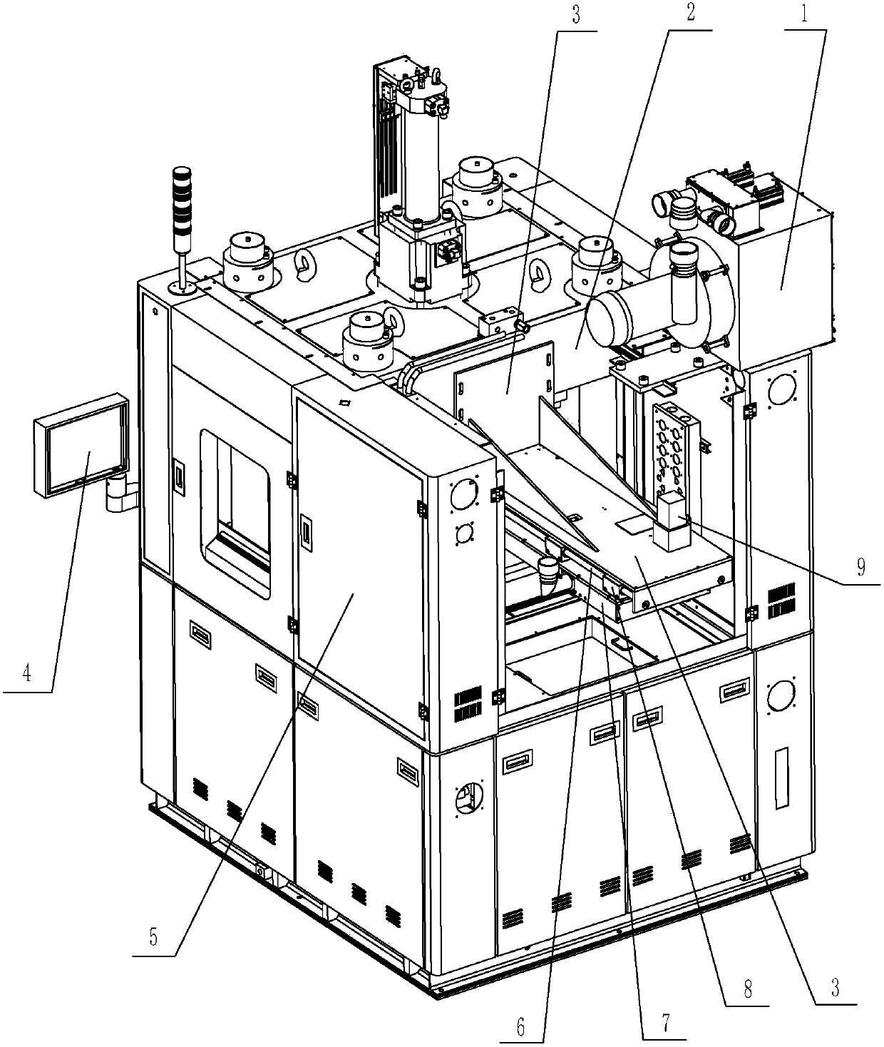
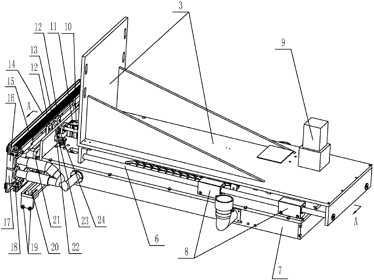
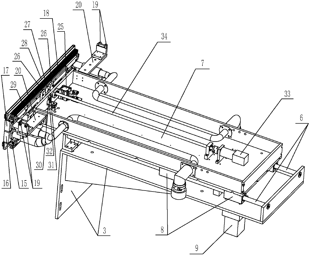
[0030] Such as Figure 1 to Figure 3As shown, in this specific embodiment, the automatic cleaning and dust suction device for plastic sealing molds of the present invention includes a fixed bracket 3, a moving plate 7, an upper cleaning brush 15, a lower cleaning brush 18, an upper dust collection box 16, and a lower dust suction box 17 And the dust collector 1, the fixed bracket 3 is fixedly installed on the upper platen 2 of the molding machine 5 by screws, the dust collector 1 is fixed on the top of the molding machine 5 by screws, and the upper dust collection box 16 is located above the lower dust collection box 17 , the upper dust collection box 16 and the lower dust collection box 17 can be connected to the front part of the moving plate 7 slidingly up...


PUM


Abstract

An automatic sweeping and dust sucking device for an encapsulation mold comprises a fixing support, a movable plate, an upper sweeping brush, a lower sweeping brush, an upper dust suction box, a lower dust suction box and a suction machine. The fixing support and the suction machine are both installed on a mold pressing machine. The upper dust suction box is located above the lower dust suction box. The upper dust suction box and the lower dust suction box are both connected to the front portion of the movable plate in an up-down sliding manner. An inner cavity of the upper dust suction box and an inner cavity of the lower dust suction box both communicate with the suction machine. The upper dust suction box is provided with an upper dust suction port, and the lower dust suction box is provided with a lower dust suction port. The movable plate is provided with a first vertical drive device and a second vertical drive device. The upper sweeping brush slides left and right along the upper dust suction box. The lower sweeping brush slides left and right along the lower dust suction box. The movable plate is provided with an upper left-right drive mechanism and a lower left-right drive mechanism. The movable plate is in front-back sliding connection with the fixing support. A front-back drive device is arranged on the fixing support. According to the automatic sweeping and dust sucking device, sweeping and dust sucking can be conducted on the parting surface of the mold at the same time, and therefore the manual workload is reduced, the production efficiency is improved, and the personal injury is avoided.

Description

Technical field: [0001] The invention relates to an integrated circuit multi-injection head plastic sealing mold, in particular to a device capable of automatically cleaning and vacuuming the upper and lower parting surfaces of the plastic sealing mold after the plastic sealing mold is opened. Background technique: [0002] With the continuous improvement of chip packaging technology and the continuous pursuit of product quality and output by packaging manufacturers, integrated circuit plastic packaging molds have also developed from traditional single-cylinder molds to multi-injection head plastic packaging molds. Integrated circuit multi-injection head plastic packaging molds are currently widely used in semiconductor factories. In order to increase efficiency and save costs, existing plastic packaging molds are getting bigger and bigger. Due to the packaging industry requirements of plastic packaging molds, the parting surface of plastic packaging molds is It is necessary...

Claims


Application Information

Patent Timeline
Patent Type & Authority Patents(China)
IPC IPC(8): B29C45/17B29C33/72
CPCB29C33/72B29C45/1753
Inventor 张作军陈小飞谢振华沙达麟兰双文
Owner ANHUI DAHUA SEMICON TECH CO LTD
Learn More