
Magnetic core after-treatment device

A post-processing device and magnetic core technology, which is applied in the direction of spraying device, surface coating liquid device, inductor/transformer/magnet manufacturing, etc., can solve the problem of low electrode bending efficiency and achieve the effect of improving post-processing efficiency

Active Publication Date: 2016-08-31
HENGDIAN GRP DMEGC MAGNETICS CO LTD
View PDF7 Cites 3 Cited by
  • Summary
  • Abstract
  • Description
  • Claims
  • Application Information

AI Technical Summary

Problems solved by technology

[0003] In order to solve the problems of local painting and low electrode bending efficiency in the magnetic core manufacturing process in the prior art, the present invention provides an automatic painting before the magnetic core electrode is bent, and automatically bends the electrode after painting, and the post-processing efficiency High core post-processing device

Method used


Image

  • Magnetic core after-treatment device
  • Magnetic core after-treatment device
  • Magnetic core after-treatment device

Examples


Embodiment Construction

[0025] The present invention will be further described below in conjunction with accompanying drawing and specific embodiment:

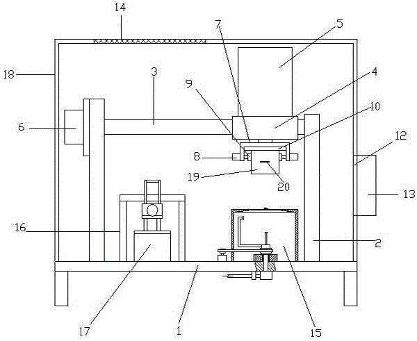
[0026] Such as image 3 and Figure 4 The shown magnetic core post-processing device includes a base plate 1, vertical support plates 2 are provided at both ends of the base plate 1, horizontal slide rails 3 are provided between the upper ends of the support plates, and sliding seats are provided on the slide rails 3 4. The upper side of the sliding seat 4 is provided with the main cylinder 5 with the shaft end facing down, and the main screw passing through the sliding seat is also provided between the support plates, and the main motor 6 that drives the main screw to rotate is provided on the support plate; the main cylinder The shaft end of the U-shaped plate is provided with a U-shaped plate 7, and both sides of the U-shaped plate 7 are provided with a horizontal clamping cylinder 8. The shaft end of the clamped cylinder is provided with a clamp...


PUM


Abstract

The invention relates to the technical field of magnetic core manufacturing and discloses a magnetic core after-treatment device. The magnetic core after-treatment device comprises a base plate. Supporting plates are arranged at the two ends of the base plate. A sliding rail is arranged between the upper ends of the supporting plates. A sliding seat is arranged on the sliding rail. A main air cylinder is arranged on the sliding seat. A main threaded rod is arranged between the supporting plates. A main motor used for driving the main threaded rod to rotate is arranged on one of the supporting plates. A U-shaped plate is arranged at the shaft end of the main air cylinder. Horizontal clamping air cylinders are arranged on the two sides of the U-shaped plate. A clamping block is arranged at the shaft end of each clamping air cylinder. An automatic paint spraying mechanism is arranged at the right end of the base plate. A supporting seat is arranged at the left end of the base plate. An electrode bending mechanism is arranged below the supporting seat. The base plate is further provided with a dust cover. An air inlet is formed in the top of the dust cover. A filter screen is arranged in the position of the air inlet. An exhaust port is formed in the side face of the dust cover. An exhaust fan is arranged in the position of the exhaust port. The magnetic core after-treatment device has the beneficial effects that automatic paint spraying can be achieved before bending of a magnetic core electrode, the electrode is automatically bent after paint spraying, and the magnetic core after-treatment efficiency is improved.

Description

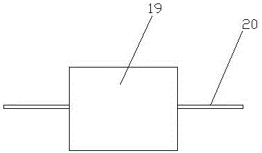
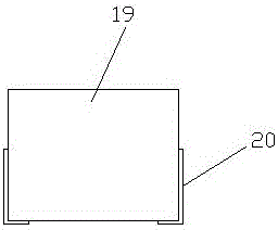
technical field [0001] The invention relates to the technical field of magnetic core manufacturing, in particular to a magnetic core post-processing device. Background technique [0002] The one-piece magnetic core usually includes a magnetic core and a coil set in the core body. Electrodes are provided at both ends of the coil. During the manufacturing process, the electrodes are welded to both ends of the coil, and then the coil and the magnetic powder are pressed together into a magnetic core, thus making a core semi-finished product, such as figure 1 As shown, the magnetic core 19 is in a cubic structure, and the two electrodes 20 extend out of the magnetic core, and the semi-finished product needs to be post-processed to form such a figure 2 Finished product shown. After the finished magnetic core is finished, a humidity test is required. In order to prevent the surface of the magnetic core from rusting during the humidity test, each surface of the finished magnetic ...

Claims


Application Information

Patent Timeline
IPC IPC(8): B21F1/00H01F41/02B05B15/12B05B13/02
CPCB05B13/0278B05B15/80B21F1/004H01F41/0246
Inventor 郭宾
Owner HENGDIAN GRP DMEGC MAGNETICS CO LTD
Learn More