Permanent magnet direct current energy adding motor

A permanent magnet DC and permanent magnet technology, which is applied in the field of permanent magnet DC energy-enhanced motors, can solve the problems of complex rotor armature structure, lack of magnetization effect, and low utilization rate, so as to improve the air gap magnetic field strength, increase and enhance The utilization level of permanent magnets and the effect of improving the utilization rate

Active Publication Date: 2016-08-24
赵鑫堂
View PDF6 Cites 2 Cited by
  • Summary
  • Abstract
  • Description
  • Claims
  • Application Information

AI Technical Summary

Problems solved by technology

[0002] A motor is a device that converts electrical energy into mechanical energy. From the perspective of energy structure, the current traditional motors can be divided into two categories: one is a motor driven by only one kind of electrical energy, and its energy structure is "one yuan", such as AC Motors, DC motors, reluctance motors, etc.; the other type is a motor driven by electric energy and permanent magnet energy, and its energy structure is "binary". Figure 1~2 , such as permanent magnet motors, permanent magnet synchronous motors, permanent magnet brushless DC motors, etc., because the binary motor increases the permanent magnet energy level from the structure, so the utilization rate of permanent magnet energy is improved, and its power saving rate is ordinary than that of the unitary motor 10-20% increase, but due to its structural limitations, there are certain deficiencies: 1. The two poles of the electric excitation core can only use one of the poles or one level to work
2. The N and S poles of the permanent magnet can only work on one pole surface or one level
3. The arrangement of permanent magnets lacks the magnetization effect, so the utilization rate is not high, the structure of the rotor armature is complex, the power consumption is high, and the temperature rises; in summary, the utilization rate of permanent magnet energy should be improved

Method used


Image

  • Permanent magnet direct current energy adding motor
  • Permanent magnet direct current energy adding motor
  • Permanent magnet direct current energy adding motor

Examples


Embodiment 1

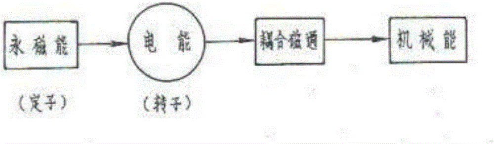
[0055] The permanent magnet DC energy-enhanced motor of the present invention adopts electronic commutation (brushless control) such as Figure 5-6 As shown: It consists of a casing 13, a permanent magnet energy generator stator pole assembly fixedly connected in the casing, a permanent magnet rotor unit, a bearing, a front end cover, a rear end cover, and electronic commutation system components connected thereto;

[0056] Among them, the stator pole assembly of the permanent magnet energy generator includes a magnet core 5 which is stacked and riveted by silicon steel sheets, the middle part of the magnet core is embedded with a winding 7, the large end face of the magnet core is pasted with a stator permanent magnet 6, and the stator permanent magnet is radially charged. Magnetism, magnetic field direction see Image 6 The middle mark is arranged side by side according to the magnetic accumulation structure. The above-mentioned parts constitute the stator pole unit of the p...

Embodiment 2

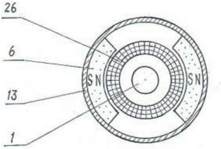
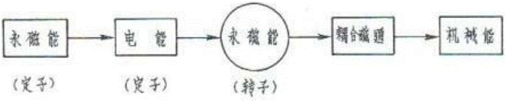
[0063] The permanent magnet DC energized motor of the present invention is as Figure 8-9 Shown; Including casing 13, permanent magnet energy generator stator pole assembly, permanent magnet rotor unit, bearing 2, front end cover 15, rear end cover 10 and the mechanical commutation (with brush control) system components;

[0064] Among them, the stator pole assembly of the permanent magnet energy generator includes: the magnet core 5 is stacked and riveted by silicon steel sheets, the middle part of the iron core is embedded with a winding 7, the large end face of the iron core is pasted with the stator permanent magnet 6, and the stator permanent magnet 6 is radially charged. The direction of magnetism and magnetic field is shown in the figure and arranged according to the magnetic accumulation structure. There are six groups of permanent magnet energy generators, which are evenly distributed according to the mechanical angle of 60 degrees. The stator permanent magnets 6 in e...


PUM


Abstract

The invention discloses a permanent magnet direct current energy adding motor. The permanent magnet direct current energy adding motor comprises an enclosure(13), a permanent magnet rotor unit, a reversing system assembly and a permanent magnet energy adding device stator pole assembly; the permanent magnet energy adding device stator pole assembly is fixed in the enclosure (13), and the permanent magnet rotor unit is arranged at the inner side of the permanent magnet energy adding device stator pole assembly; the permanent magnet rotor unit is installed on a front end cover (15) and a rear end cover (10) through a bearing (2); the front end cover (15) and the rear end cover (10) are respectively installed on the front end and the rear end of the enclosure (13); and a motor shaft (1) of the permanent magnet rotor unit is further equipped with the reversing system assembly. The permanent magnet direct current energy adding motor provided by the invention has the advantages of being high in permanent magnet energy utilization, obvious in energy-saving effect, simple in structure and low in cost.

Description

technical field [0001] The invention belongs to the technical field of electrical engineering, and in particular relates to a permanent magnet DC energized motor. Background technique [0002] A motor is a device that converts electrical energy into mechanical energy. From the perspective of energy structure, the current traditional motors can be divided into two categories: one is a motor driven by only one kind of electrical energy, and its energy structure is "one yuan", such as AC Motors, DC motors, reluctance motors, etc.; the other type is a motor driven by electric energy and permanent magnet energy, and its energy structure is "binary". Figure 1~2 , such as permanent magnet motors, permanent magnet synchronous motors, permanent magnet brushless DC motors, etc., because the binary motor increases the permanent magnet energy level from the structure, so the utilization rate of permanent magnet energy is improved, and its power saving rate is ordinary than that of the u...

Claims


Application Information

Patent Timeline
Patent Type & Authority Applications(China)
IPC IPC(8): H02K23/04H02K23/00H02K1/17H02K1/27H02K23/66
CPCH02K1/17H02K1/2706H02K23/00H02K23/04H02K23/66
Inventor 赵鑫堂拓海亮曾光华王勤生
Owner 赵鑫堂
Why Eureka
Try Eureka