A Vortex Controllable Optical Transmitter Based on Miniature Ring Resonator

A ring resonant cavity and optical transmitter technology, which is applied in the direction of instruments, light guides, optics, etc., can solve the problems of low light transmission efficiency on fusion surfaces, achieve the effects of reducing leakage, improving coupling efficiency, and reducing crosstalk

Active Publication Date: 2019-05-10
FUZHOU UNIV
View PDF10 Cites 0 Cited by
  • Summary
  • Abstract
  • Description
  • Claims
  • Application Information

AI Technical Summary

Problems solved by technology

The third is to use the super-nano interface existing on the fusion surface to generate vortex light. The super-nano interface can produce phase mutations on two different media, thereby forming irregular light reflection or light refraction. method, but the light transmission efficiency of the fused surface is very low, and it faces many challenges in practical applications
At present, there is still a lack of integrated small vortex light emitters that can flexibly control the vortex direction

Method used


Image

  • A Vortex Controllable Optical Transmitter Based on Miniature Ring Resonator
  • A Vortex Controllable Optical Transmitter Based on Miniature Ring Resonator
  • A Vortex Controllable Optical Transmitter Based on Miniature Ring Resonator

Examples


Embodiment Construction

[0035] The technical solution of the present invention will be specifically described below in conjunction with the accompanying drawings.

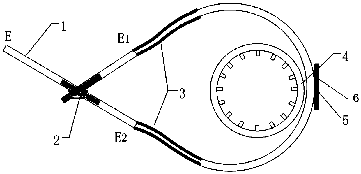
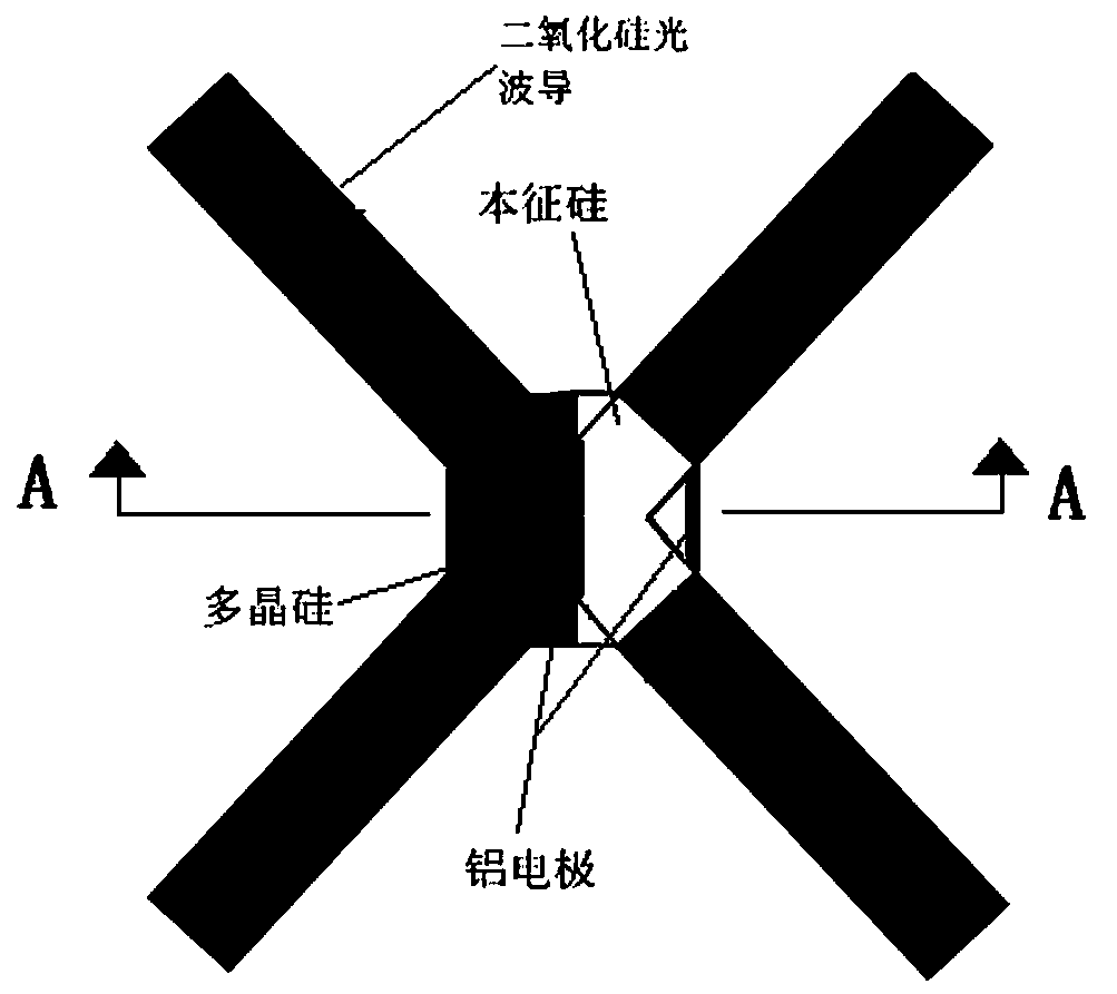
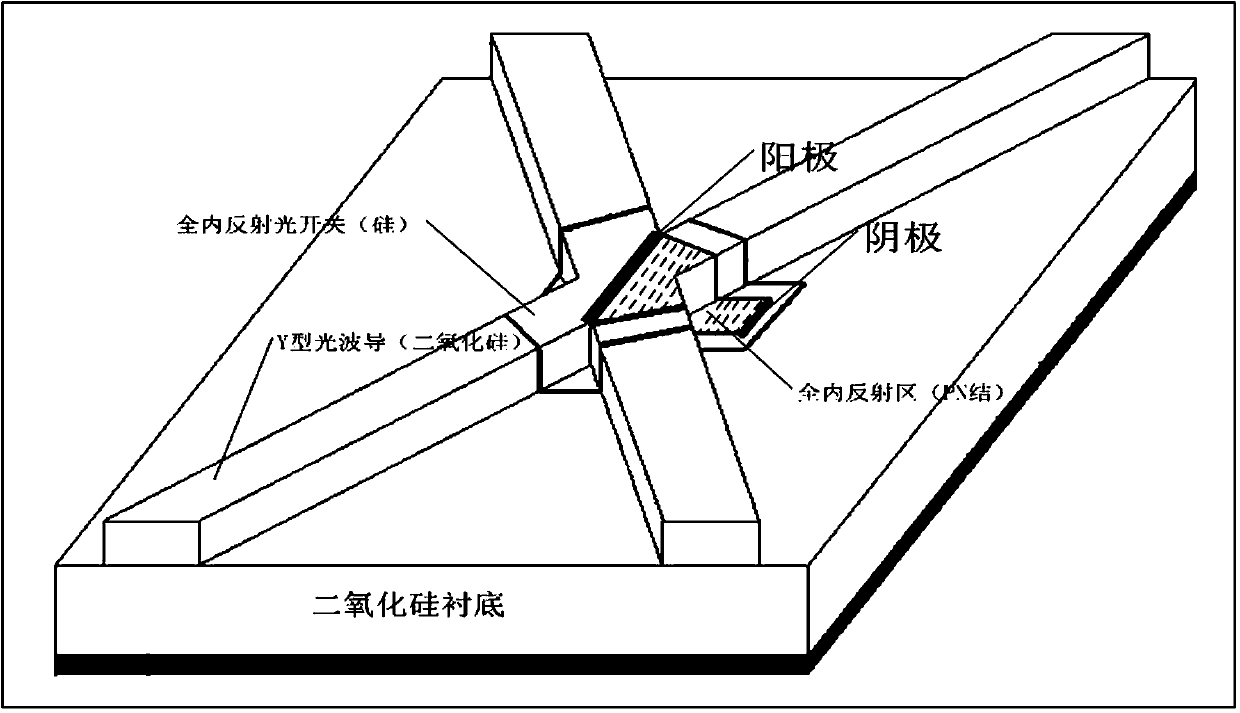
[0036] The invention provides a vortex controllable light emitter based on a miniature ring resonant cavity, such as figure 1 As shown, it includes a Y-shaped optical waveguide 1, an arc-shaped optical waveguide coupler 5 and a ring resonant cavity 4; a Si-based junction for controlling the reflection and transmission of incident light is arranged on the bifurcation point of the Y-shaped optical waveguide 1 type optical switch 2; the Y-type optical waveguide passes through the S-type bending waveguide attenuator 3 used to reduce the crosstalk of the Si-based junction type optical switch, that is, the first S-type bending waveguide attenuator and the second S-type bending waveguide attenuator respectively , connected to the arc-shaped optical waveguide coupler; the arc-shaped optical waveguide coupler is inscribed with the ring resonant ca...


PUM

PropertyMeasurementUnit
radiusaaaaaaaaaa
widthaaaaaaaaaa
lengthaaaaaaaaaa

Abstract

The invention relates to a micro annular resonant cavity based vortex-controllable light transmitter. The micro annular resonant cavity based vortex-controllable light transmitter comprises a Y type light waveguide, an arc-shaped light waveguide coupler and an annular resonant cavity, wherein an Si-based junction type optical switch for controlling reflection and transmission of incident light is arranged on a branching node of the Y type light waveguide; the Y type light waveguide is connected to the arc-shaped light waveguide coupler through a first S type bent waveguide attenuator and a second S type bent waveguide attenuator; the first S type bent waveguide attenuator and the second S type bent waveguide attenuator are used for reducing the crosstalk of the Si based junction type optical switch; the arc-shaped light waveguide coupler is internally tangential to the annular resonant cavity, and a silicon-based total reflector for coupling an incident light beam from the arc-shaped light waveguide coupler into the annular resonant cavity is arranged at a tangential point. The micro annular resonant cavity based vortex-controllable light transmitter can be realized through a mature semiconductor Si process, can be used as an encoding and decoding device of a vortex light communication system, and is high in economic value.

Description

technical field [0001] The invention relates to the technical field of semiconductor optoelectronic devices, in particular to a vortex controllable light emitter based on a miniature ring resonant cavity. Background technique [0002] Since the discovery of vortex light, various experiments to explore and prepare vortex light have been a research hotspot in this field, and a variety of technologies for generating vortex light have been developed successively, such as spiral phase plates, computer holograms and cylindrical converters, etc. However, These technologies for generating vortex light are based on complex and huge optical systems, which are difficult to be compatible with contemporary integrated optical communication technologies. In recent years, the use of emerging micro-nano semiconductor technology to prepare miniature integrated vortex optical devices to meet the needs of today's optical communication technology has attracted the attention of the industry. [...

Claims


Application Information

Patent Timeline
Patent Type & Authority Patents(China)
IPC IPC(8): G02B6/125G02B6/293G02B6/35G02B6/26G02F1/035
CPCG02B6/125G02B6/266G02B6/29338G02B6/3504G02F1/035
Inventor 黄春晖王超
Owner FUZHOU UNIV
Why Eureka
Try Eureka