
Colorimetric dish for measuring scattered spectrum and optical system of colorimetric dish

A cuvette and spectrum technology, applied in the field of cuvette and its optical system, can solve the problems of entering the photoelectric detector, low light utilization rate, and difficulty in avoiding excitation light, etc., and achieves wide application range, easy popularization and application, structural simple effect

Inactive Publication Date: 2016-08-24
GUANGXI UNIVERSITY OF TECHNOLOGY
View PDF8 Cites 2 Cited by
  • Summary
  • Abstract
  • Description
  • Claims
  • Application Information

AI Technical Summary

Problems solved by technology

[0003] The technical problem to be solved by the present invention is to provide a cuvette for measuring the scattering spectrum and its optical system, so as to solve the shortcomings of the prior art that it is difficult to prevent the excitation light from entering the photodetector and the light utilization rate is low

Method used


Image

  • Colorimetric dish for measuring scattered spectrum and optical system of colorimetric dish
  • Colorimetric dish for measuring scattered spectrum and optical system of colorimetric dish
  • Colorimetric dish for measuring scattered spectrum and optical system of colorimetric dish

Examples


Embodiment 1

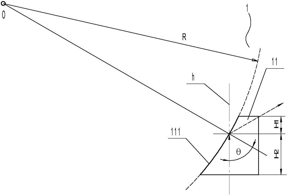
[0029] A kind of cuvette 1 for measuring the scattering spectrum, comprising cuvette body 11, the longitudinal section of the cuvette body 11 is a right-angled trapezoidal structure with oblique waist and curved concave surface 111, the incident angle of the cuvette body 11 is θ is 60°, which can cause total reflection of incident light in samples with a refractive index greater than 1.16. The arc concave surface 111 intersects the vertical line h of the cuvette body 11 at the position H1:H2=3:7 in the vertical direction. For a cuvette of 10mm size, the focal point O of the arc concave surface is to The distance between the curved concave surface (that is, the radius R of the curved concave surface) is 89.14mm. The incident excitation light enters from the center of the bottom surface of the cuvette, is totally reflected at a distance of 7mm from the bottom surface of the cuvette, and emits from the edge of the top surface in the upper right corner. For samples with a refracti...

Embodiment 2

[0032] An optical system for measuring the scattering spectrum, comprising an excitation light source 2, a slit I3, a cuvette, and a photodetector 4 sequentially arranged on the optical path, and the cuvette is the one described in Embodiment 1 for Measure the cuvette 1 of scattering spectrum, the concrete structure of this cuvette is as follows:

[0033] A kind of cuvette 1 for measuring the scattering spectrum, comprising cuvette body 11, the longitudinal section of the cuvette body 11 is a right-angled trapezoidal structure with oblique waist and curved concave surface 111, the incident angle of the cuvette body 11 is θ is 60°, which can cause total reflection of incident light in samples with a refractive index greater than 1.16. The arc concave surface 111 intersects the vertical line h of the cuvette body 11 at the position H1:H2=3:7 in the vertical direction. For a cuvette of 10mm size, the focal point O of the arc concave surface is to The distance between the curved ...


PUM


Abstract

The invention discloses a colorimetric dish for measuring a scattered spectrum and an optical system of the colorimetric dish. The colorimetric dish comprises a colorimetric dish body, wherein the longitudinal cross section of the colorimetric dish body is of a right trapezoid structure of which the oblique lumbar is an arch-shaped concave surface; all surfaces of the colorimetric dish body are transparent; an incident angle theta greater than 56 degrees is formed; the arch-shaped concave surface is intersected with the perpendicular bisector of the colorimetric dish body in a position of 3:7 in a vertical direction. The optical system comprises an excited light source, a slit I, the colorimetric dish body and a photoelectric detector, wherein the excited light source and the slit I are arranged on one side of the plane of the colorimetric dish body; the photoelectric detector is arranged at the focal point of the arch-shaped concave surface. By utilizing the total reflection principle, the gap between excited light and scattered light is expanded, the excited light is prevented from entering the detector, and meanwhile the scattered light is gathered through the arch-shaped concave surface, so that the luminous flux entering the detector and the light utilization are increased, and the device can be applied to measurement on scattered light generated through excitation of fluorescent light, phosphorescence or Raman light of a liquid sample.

Description

technical field [0001] The invention relates to a cuvette and its optical system, in particular to a cuvette for measuring scattering spectrum and its optical system. Background technique [0002] Spectral measurements can take the form of transmission, reflection, diffusion, etc., as well as scattered light generated by optical excitation such as fluorescence and Raman light. The intensity of scattered light relative to excitation light is several orders of magnitude lower for fluorescence and even lower for Raman light. Therefore, when measuring the scattering spectrum, it is necessary to increase the intensity of the excited light as much as possible, and at the same time avoid the excitation light from entering the detector as much as possible. In order to avoid the influence of the excitation light, the incident light path and the detection light path are vertical at present, and the excited scattered light is detected from the direction least affected by the excitatio...

Claims


Application Information

Patent Timeline
IPC IPC(8): G01N21/01G01N21/64G01N21/65
CPCG01N21/01G01N21/64G01N21/65G01N2021/0112
Inventor 粟晖姚志湘
Owner GUANGXI UNIVERSITY OF TECHNOLOGY
Learn More