
Multi-condenser and double-return-air bypass dehumidification fresh air unit and air conditioning method

A fresh air unit and return air bypass technology, which is applied to control input related to air characteristics, air conditioning system, space heating and ventilation details, etc., can solve problems such as insufficient heating, energy waste, and difficulty in meeting cooling capacity requirements. Achieve the effect of increasing the ambient temperature, reducing the condensation temperature, and avoiding the loss of cooling capacity

Active Publication Date: 2016-08-24
JIANGSU HUIJU ARCHITECTURE TECH CO LTD
View PDF5 Cites 34 Cited by
  • Summary
  • Abstract
  • Description
  • Claims
  • Application Information

AI Technical Summary

Problems solved by technology

[0003] The use of condensation heat by traditional fresh air dehumidifiers is mainly to reheat the fresh air after cooling and dehumidification. Although it solves the problem of huge energy consumption caused by relying on electric heating, the use of condensation and reheating offsets part of the cooling capacity of the unit to a certain extent. The offset of cold and heat results in a waste of energy; in terms of the use of condensation heat, some scholars propose to place the outdoor air-cooled condenser on the indoor exhaust side, and use the indoor exhaust air with a higher temperature as the heat source of the unit in winter , to solve the disadvantages of insufficient heating in winter, but it brings a new problem, that is, in summer, the cooling capacity is difficult to meet the requirements, and it is far from enough to rely on indoor exhaust as a cooling source
[0004] For this reason, the emergence of a new type of dehumidifier is urgently needed to solve the problems of the above-mentioned existence.

Method used


Image

  • Multi-condenser and double-return-air bypass dehumidification fresh air unit and air conditioning method

Examples


Embodiment Construction

[0046] In order to more clearly illustrate the embodiments of the present invention or the technical solutions in the prior art, the specific implementation manners of the present invention will be described below with reference to the accompanying drawings. Obviously, the accompanying drawings in the following description are only some embodiments of the present invention, and those skilled in the art can obtain other accompanying drawings based on these drawings and obtain other implementations.

[0047] In order to make the drawing concise, each drawing only schematically shows the parts related to the present invention, and they do not represent the actual structure of the product. In addition, to make the drawings concise and easy to understand, in some drawings, only one of the components having the same structure or function is schematically shown, or only one of them is marked. Herein, "a" not only means "only one", but also means "more than one".

[0048] In Embodim...


PUM


Abstract

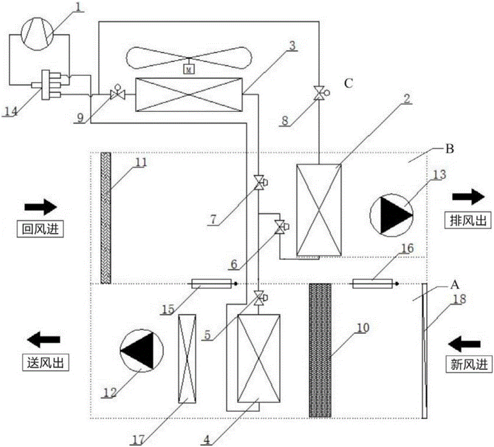
The invention relates to a multi-condenser and double-return-air bypass dehumidification fresh air unit and an air conditioning method. The multi-condenser and double-return-air bypass dehumidification fresh air unit comprises an air feed channel and an exhaust channel. A first heat exchanger and an air feeder are sequentially arranged at the position of the air feed channel. A second heat exchanger and an exhaust fan are sequentially arranged at the position of the exhaust channel. The second heat exchanger is connected with an auxiliary heat exchanger. A first return air bypass valve and a second return air bypass valve are arranged between the air feed channel and the exhaust channel. According to the multi-condenser and double-return-air bypass dehumidification fresh air unit, during refrigerating, the second heat exchanger serves as a condenser, a refrigerant is condensed through the indoor low-temperature exhaust air, the condensation temperature of the unit is reduced, and reheating is conducted through mixing of bypass return air and low-temperature fed air on the air feed side so that cooling capacity losses caused by cold and heat offset can be avoided; in a heating inner circulation mode, an outdoor unit can be started to rapidly increase the indoor environment temperature; and in an outer circulation mode, the second heat exchanger serves as an evaporator, the refrigerant is made to be evaporated through the heat of indoor exhaust air, the evaporation pressure and the heating capacity of the unit are increased, the power consumption of the unit is reduced, and the frosting risk of the unit is avoided.

Description

technical field [0001] The invention relates to the technical field of air conditioning and energy utilization, in particular to a dehumidification fresh air unit with multiple condensers and double return air bypasses and an air conditioning method. Background technique [0002] In the existing technology, the condensation heat of the air conditioning unit can reach 1.15 to 1.3 times of the cooling capacity, and a large amount of condensation heat will be directly discharged into the atmosphere, and only rely on outdoor high-temperature air to condense it, not only the condensation effect is not good, Moreover, the emission of these heats increases the temperature of the surrounding environment, causing serious environmental heat pollution, and at the same time, this part of the heat will be lost in vain, resulting in a large waste of energy. If the condensation heat released by the air conditioning unit is recycled, and the indoor exhaust air temperature is lower in summer...

Claims


Application Information

Patent Timeline
Patent Type & Authority Applications(China)
IPC IPC(8): F24F3/14F24F11/00F24F13/30
CPCF24F3/14F24F11/30F24F13/30F24F2110/10
Inventor 张国华许亚兵彭强强
Owner JIANGSU HUIJU ARCHITECTURE TECH CO LTD
Learn More