
Compound buckled wood floors

A wooden floor and buckle wood technology, which is applied to floors, buildings, building structures, etc., can solve problems such as warping, deformation, mutual extrusion, and gaps that cannot be adjusted

Inactive Publication Date: 2016-08-24
BAROQUE WOOD IND ZHONGSHAN CO LTD
View PDF7 Cites 9 Cited by
  • Summary
  • Abstract
  • Description
  • Claims
  • Application Information

AI Technical Summary

Problems solved by technology

Not only that, the existing wooden floors are two pieces spliced ​​together, the gap in the middle cannot be adjusted, it is easy to make the two wooden floors squeeze each other in a humid environment, causing warping and deformation

Method used


Image

  • Compound buckled wood floors
  • Compound buckled wood floors
  • Compound buckled wood floors

Examples


Embodiment 1

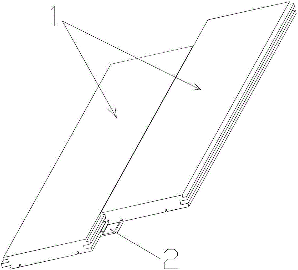
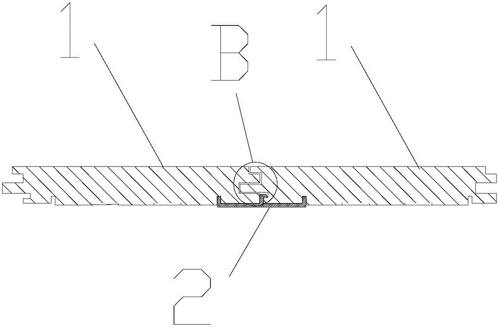
[0030] Figure 1 to Figure 6 Schematically shows a compound buckle wood flooring according to an embodiment of the present invention. As shown in the figure, the device includes a wooden floor 1 and a fastener 2 .

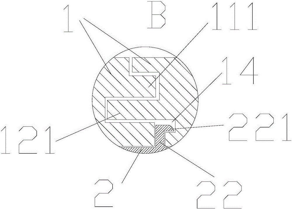
[0031] Wherein, a first groove 11 and a second groove 12 are respectively provided on opposite sides of the wooden floor 1 . After two adjacent wooden floorboards 1 are connected to each other through the first groove 11 and the second groove 12 , the wooden floorboards 1 can move along their lengthwise or widthwise directions.

[0032] The two sides opposite to the back of the wooden floor 1 are respectively provided with slide grooves 13 parallel to the edges thereof.

[0033] In this embodiment, the first tongue and groove 11 includes a first tongue 111 and a first tongue and groove 112 respectively arranged along the thickness direction of the wood floor 1 . Wherein, the first tongue 111 is located above the first tongue groove 112 . The second tongue and g...

Embodiment 2

[0059] Figure 7 Schematically shows a compound buckle wooden floor according to another embodiment of the present invention. As shown in the figure, the difference from Embodiment 1 is that a tongue or a tongue and groove are provided on both sides of the wooden floor 1, thereby forming a single tenon-and-groove structure.

[0060] In this embodiment, an overhead groove 15 is also provided on the back of the wooden floor 1 . The depth of the overhead groove 15 is 2-5 mm, which is used to isolate the main body of the wooden floor 1 from the ground. In this way, a channel for air flow can be formed under the wooden floor 1 , thereby avoiding local accumulation of humidity and temperature under the wooden floor 1 and causing strong deformation of the bottom plate. This kind of wooden floor is especially suitable for installation in an environment with high humidity on the ground or in a place where floor heating is installed.


PUM

PropertyMeasurementUnit
Depthaaaaaaaaaa

Abstract

The invention discloses compound buckled wood floors which comprise wood floor bodies and buckle pieces, wherein a first rabbet and a second rabbet are respectively arranged on two opposite sides of each wood floor body; after two adjacent wood floor bodies are connected with each other through the first rabbets and the second rabbets, the wood floor bodies can move in the length direction or the width direction; sliding chutes parallel to the edges of the wood floor bodies are respectively formed in two opposite sides on the back surfaces; the buckle pieces are mounted on the back surfaces of the wood floor bodies; parallel sliding rails are arranged on two sides of the buckle pieces and are matched with the sliding chutes; central boards parallel to the sliding rails are further arranged in the middles of the buckle pieces and are positioned between every two adjacent wood floor bodies. According to the compound buckled wood floors, by the adoption of a structure that the buckle pieces are matched with the wood floor bodies, the wood floor bodies cannot be damaged and can be assembled, disassembled and reused conveniently; two adjacent wood floor bodies are plugged through the rabbets and then are fixedly connected through the buckle pieces. The buckle pieces transmit fixed acting force of the wood floor bodies to the middle parts, so that cracking of the edge parts of the wood floor bodies can be effectively avoided.

Description

technical field [0001] The invention relates to a wooden floor, in particular to a compound buckle wooden floor. Background technique [0002] At present, most of the wooden floors laid are lock floors. The locking floor uses the locking structure formed by the wedge-shaped tongue and groove on both sides to insert and fix each other. However, the wedge-shaped tongue and tenon groove of the lock floor are difficult to process, and the material yield is low, wasting a large amount of non-renewable precious wood resources. During the processing and drying process of wood flooring, the edge dries much faster than the inside, and the moisture at the edge reaches below the fiber saturation point and shrinks, while the moisture inside does not need to shrink, so the edge is affected by the overall moisture, The tensile stress is larger. Moreover, after the locking floor is connected and fixed, the wedge-shaped tongue exerts a large tension force on the tenon groove, so that the...

Claims


Application Information

Patent Timeline
IPC IPC(8): E04F15/04
CPCE04F15/04
Inventor 徐华勇周兴华吴永禄戴维德
Owner BAROQUE WOOD IND ZHONGSHAN CO LTD
Learn More