


Quick Research
Generate reliable direction feasibility study reports for your R&D in just a few steps.

Technical Q&A
Discover and master advanced knowledge NOW. Basics, ideas, possibilities, all at once.

Find Solutions
As an expert in R&D theories, this can generate solutions to your technical problems instantly.

Evaluate Feasibility
Analyze your overall solution with one click, know your potential R&D risks in advance.

Monitor Landscape
Get weekly tech updates, stay abreast of the latest tech innovations and key insights.
Automatic split-type handheld syringe
An auto-injector and split-type technology, which is applied in the direction of auto-injectors, syringes, hypodermic injection equipment, etc., can solve the problems of continuous supply of vaccines, slow injection rate, and damage to the injection site, etc., and achieve long-term power supply and injection dose. Accurate effect of adjusting and injecting dosage
- Summary
- Abstract
- Description
- Claims
- Application Information
AI Technical Summary
Problems solved by technology
Method used
Image

Examples
Embodiment 1
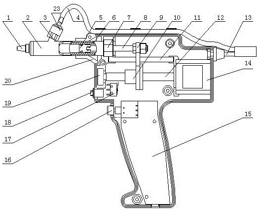
[0030] refer to figure 1 and figure 2 , the split-type hand-held automatic injector in the embodiment of the present invention includes a housing 20, an electrical system, a screw nut transmission mechanism, an injection tube, a liquid suction joint 23 and a liquid inlet hose 4, and the liquid inlet hose 4 is made of rubber material, one end is connected with the upper end of the liquid suction joint 23, and the other end is connected with the large-dose vaccine bottle.
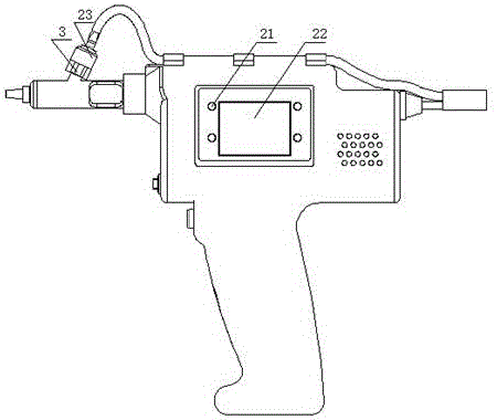
[0031] Described circuit system comprises injection button 16, circuit board 15, motor 14, limit switch 17, power switch 18, selection button 21, display panel 22 and external wiring 13, described injection button 16, motor 14, limit switch 17 , the power switch 18 and the display panel 22 are fixed at different positions of the casing 20, and are all electrically connected with the circuit board 15; the selection button 21 is fixed around the display panel 22; one end of the external wire 13 is connected t...
Embodiment 2
[0043] refer to Figure 4 and Figure 5, the split-type hand-held automatic injector in the embodiment of the present invention includes a housing 20, an electrical system, a screw nut transmission mechanism, an injection tube, and a first medicine bottle holder 24, and one end of the first medicine bottle holder 24 is connected to the inlet The liquid port 3 is threaded, and the other end is used to insert a small-dose vaccine bottle.
[0044] Described circuit system comprises injection button 16, circuit board 15, motor 14, limit switch 17, power switch 18, selection button 21, display panel 22 and external wiring 13, described injection button 16, motor 14, limit switch 17 , the power switch 18 and the display panel 22 are fixed at different positions of the casing 20, and are all electrically connected with the circuit board 15; the selection button 21 is fixed around the display panel 22; one end of the external wire 13 is connected to the power switch 18, and the other...
Embodiment 3
[0056] refer to Figure 6 and Figure 7 , the split-type hand-held automatic injector in the embodiment of the present invention includes a housing 20, an electrical system, a screw nut transmission mechanism, an injection tube, and a second medicine bottle holder 25, and one end of the first medicine bottle holder 25 is connected to the inlet The liquid port 3 is threaded, and the other end is used to insert a small-dose vaccine bottle.
[0057] Described circuit system comprises injection button 16, circuit board 15, motor 14, limit switch 17, power switch 18, selection button 21, display panel 22 and external wiring 13, described injection button 16, motor 14, limit switch 17 , the power switch 18 and the display panel 22 are fixed at different positions of the casing 20, and are all electrically connected with the circuit board 15; the selection button 21 is fixed around the display panel 22; one end of the external wire 13 is connected to the power switch 18, and the oth...
PUM
 Abstract
Description
Claims
Application Information
 - R&D Engineer
- R&D Manager
- IP Professional
- Industry Leading Data Capabilities
- Powerful AI technology
- Patent DNA Extraction
Browse by: Latest US Patents, China's latest patents, Technical Efficacy Thesaurus, Application Domain, Technology Topic, Popular Technical Reports.
© 2024 PatSnap. All rights reserved.Legal|Privacy policy|Modern Slavery Act Transparency Statement|Sitemap|About US| Contact US: help@patsnap.com