
drill

A drill bit and drill bit shaft technology, applied in twist drills, drilling tool accessories, drilling/drilling equipment, etc., can solve problems such as low efficiency, reduced drill bit striking efficiency, and time-consuming perforation, so as to improve work efficiency and prevent processing. Deterioration of accuracy, effect of realizing weight

Active Publication Date: 2017-10-10
MIYANAGA KK
View PDF7 Cites 0 Cited by
  • Summary
  • Abstract
  • Description
  • Claims
  • Application Information

AI Technical Summary

Problems solved by technology

In addition, there is also a problem of inefficiency from the point of view of the reduction in the efficiency of the hammer hitting the drill bit during the piercing operation, which causes the piercing to take time, etc.

Method used


Image

  • drill
  • drill
  • drill

Examples


Embodiment Construction

[0037] Hereinafter, embodiments will be described with reference to the drawings. The same or corresponding parts are denoted by the same symbols in all the drawings, and repeated detailed explanations will be omitted.

[0038] (first embodiment)

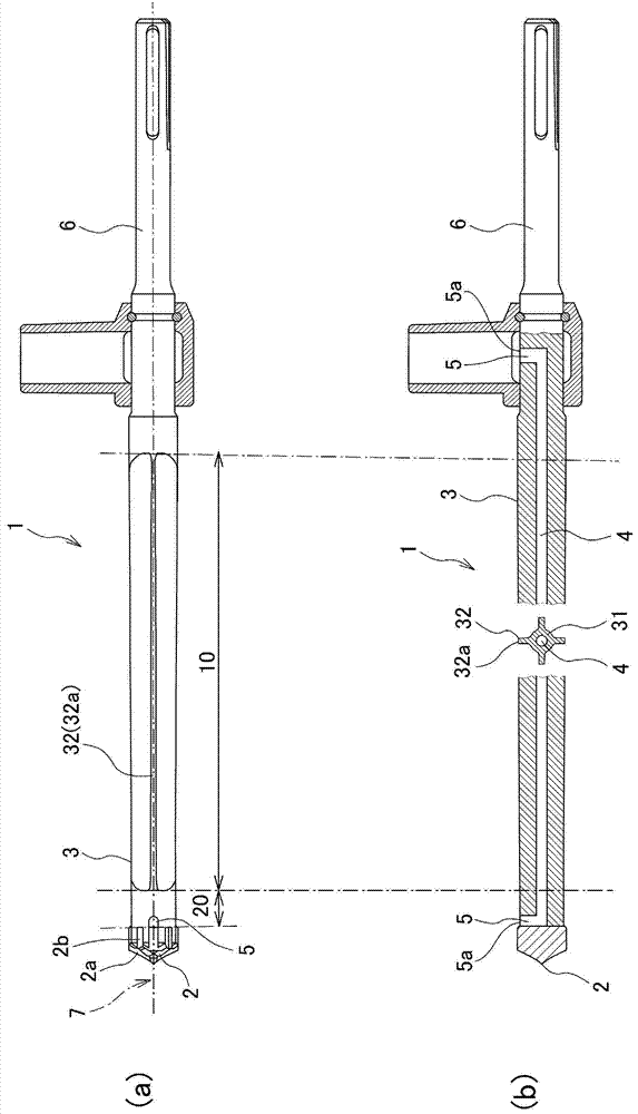
[0039] figure 1 (a) is a plan view showing a structural example of the drill of the present invention. again, figure 1 (b) is a longitudinal sectional view of the drill bit of the present invention. Also, in figure 1 In (a) and (b), the direction parallel to the central axis of the drill bit is called "axial direction", and the direction perpendicular to the central axis of the drill bit is called "radius direction". The direction of the arc at the center is called "circumferential direction". Also, for convenience of description, the "axial direction" is sometimes referred to as the front-rear direction. In this case, the direction in which the pointed portion of the drill is located is referred to as the front direction, and...


PUM


Abstract

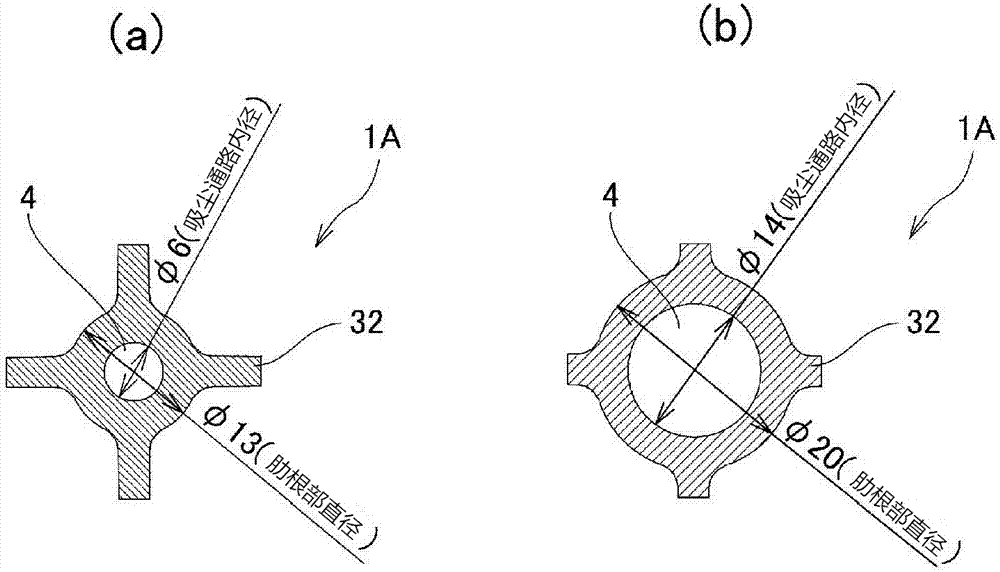
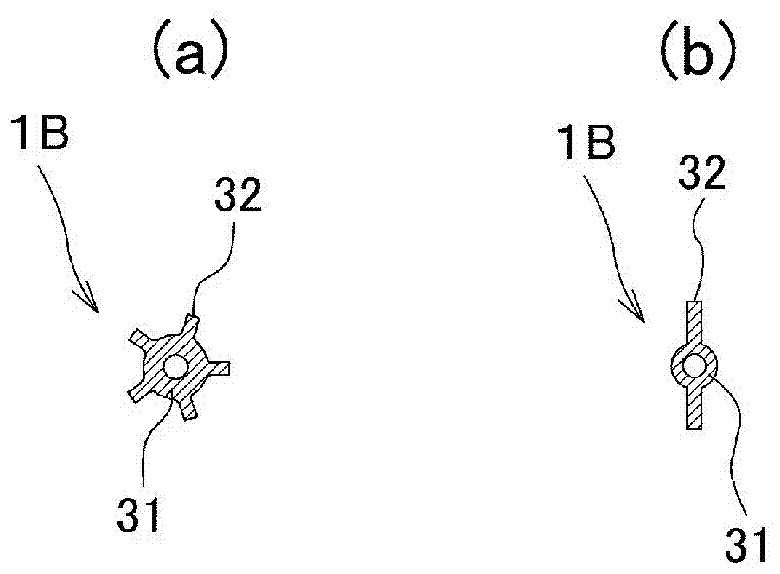
A drill bit includes a pointed portion and a bit shaft portion. A dust suction passage is formed on the shaft of the drill bit. A hole having an opening is formed in a portion near the tip of the tip or the drill shaft. The drill shaft has a first portion having a core and ribs. The core portion extends in the axial direction and is thinner than the pointed portion. The rib protrudes radially outward from the side of the core and extends along the entire length of the first portion. The dust suction passage passes through the core in the axial direction.

Description

technical field [0001] The invention relates to a drill suitable for drilling cement or stone. Background technique [0002] When perforating cement or stone, etc., a drill bit is used as a perforating tool. Drills are mainly mounted on power tools such as hammer drills. During the perforation operation, the hammer gives the drill bit both the striking force in the direction of the axis and the rotational moment, so as to perforate. [0003] The drill is formed with a dust suction passage for discharging cutting chips generated by the piercing work from the cutting hole while performing the cutting work. [0004] Prior art literature: [0005] Patent documents: [0006] Patent Document 1: International Publication No. WO2011 / 145270. Contents of the invention [0007] Problems to be solved by the invention: [0008] However, due to the heavy weight of the conventional drill bit, the work efficiency was low. In addition, there is also a problem of inefficiency in term...

Claims


Application Information

Patent Timeline
Patent Type & Authority Patents(China)
IPC IPC(8): B28D1/14
CPCB23B2251/50B28D7/02B23B51/02B23B51/06B23B2226/75B23B2251/241B23B2251/406B25D2250/211B25D17/02B28D1/146B25D17/20B25D2250/111
Inventor 宫永昌明
Owner MIYANAGA KK
Learn More