
Dual-gradually-changed transitional waveguide applied to millimeter and higher frequency point coupled cavity traveling-wave tube

A transitional waveguide and coupling cavity technology, applied in the field of waveguide structure, can solve problems such as reflection, and achieve the effect of overcoming self-excited oscillation

Inactive Publication Date: 2016-08-17
NO 12 RES INST OF CETC
View PDF5 Cites 5 Cited by
  • Summary
  • Abstract
  • Description
  • Claims
  • Application Information

AI Technical Summary

Problems solved by technology

[0007] In addition, in the traditional waveguide structure, the opening angle of the waist-shaped slot of the slow-wave line transition coupling cavity is larger than that of the main coupling cavity.

Method used


Image

  • Dual-gradually-changed transitional waveguide applied to millimeter and higher frequency point coupled cavity traveling-wave tube
  • Dual-gradually-changed transitional waveguide applied to millimeter and higher frequency point coupled cavity traveling-wave tube
  • Dual-gradually-changed transitional waveguide applied to millimeter and higher frequency point coupled cavity traveling-wave tube

Examples


Embodiment 1

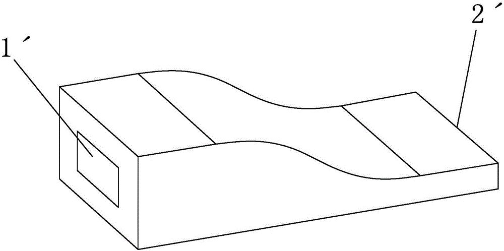
[0047] Such as Figures 6 to 10 As shown, this embodiment provides a double-tapered transition waveguide 1 used in millimeter wave and higher frequency point-coupled cavity traveling wave tubes. The transition waveguide 1 has a first port 11 and a second port 12. The first port Width L of port 11 1 greater than the width L of the second port 12 3 , the height L of the first port 11 2 greater than the height L of the second port 12 4 . The top surface 131 of the waveguide cavity 13 of the transition waveguide 1 is arranged as a gradually changing curved surface along the axial direction of the waveguide cavity 13, and the bottom surface 132 of the waveguide cavity 13 is arranged on a plane along the axial direction of the waveguide cavity 13, so The two side wall surfaces 133, 134 of the waveguide cavity 13 are arranged on symmetrical slopes along the axial direction of the waveguide cavity 13;

[0048] Further, the radial section of the waveguide cavity 13 is rectangular,...

Embodiment 2

[0051] Such as Figures 11 to 16 As shown, this embodiment provides a double-tapered transition waveguide 1 used in millimeter wave and higher frequency point-coupled cavity traveling wave tubes. The transition waveguide 1 has a first port 11 and a second port 12. The first port Width L of port 11 1 greater than the width L of the second port 12 3 , the height L of the first port 11 2 greater than the height L of the second port 12 4 .

[0052] The waveguide cavity 13 of the transitional waveguide 1 includes a first equal-diameter cavity 131 matched with the mouth end of the first port 11, a variable-diameter cavity 132, and a first equal-diameter cavity 132 matched with the mouth end of the second port 12 arranged in sequence. Two isometric chambers 133 .

[0053] The top surface 1321 of the variable diameter cavity 132 is arranged as a gradually changing curved surface along the axial direction of the waveguide cavity 13, and the bottom surface 1322 of the variable diam...

Embodiment 3

[0058] The difference between this embodiment and Embodiment 1 is that: the bottom surface of the waveguide cavity is arranged as a gradually changing curved surface along the axial direction of the waveguide cavity.


PUM


Abstract

The invention discloses a dual-gradually-changed transitional waveguide applied to a millimeter and higher frequency point coupled cavity traveling-wave tube. The transitional waveguide is equipped with a first port and a second port, wherein the width L1 of the first port is greater than the width L3 of the second port; and the height L2 of the first port is greater than the height L4 of the second port. By adoption of the transitional waveguide, the reflection of the waveguide input end and the waveguide output end is effectively restrained, and self-oscillation caused by matching defects is overcome.

Description

technical field [0001] The invention relates to a waveguide structure, in particular to a double tapered transition waveguide used in millimeter wave and higher frequency point coupling cavity traveling wave tubes. Background technique [0002] The coupling cavity and the dedicated input and output waveguide coupling structure in the folded waveguide traveling wave tube are mainly used as the entrance and exit of the traveling wave tube to amplify the signal. Its application can significantly improve the matching characteristics of the high-frequency point traveling wave tube, suppress oscillation, and improve the reliability of the traveling wave tube. [0003] In this technical field, the slow-wave line of the traveling wave tube is a transmission line, and the high-frequency energy can pass from the input end to the output end, or from the output end to the input end, which means that there is an internal feedback channel in the traveling wave tube. When there is a refle...

Claims


Application Information

Patent Timeline
Patent Type & Authority Applications(China)
IPC IPC(8): H01P3/12H01J23/36
CPCH01P3/12H01J23/36
Inventor 苏小刚吴钢隋高英
Owner NO 12 RES INST OF CETC
Learn More