
Optical add drop multiplexer based on antisymmetric multimode waveguide Bragg grating

A technology of optical add-drop multiplexer and waveguide grating, which is applied in the direction of wavelength division multiplexing system, multiplexing communication, optical multiplexing system, etc., which can solve the problem of high precision of manufacturing process and difficult wavelength selection , filter bandwidth and other problems, to achieve the effect of convenient low-cost manufacturing, easy integration and expansion, and simple device design structure

Inactive Publication Date: 2016-08-17
LONGYAN UNIV
View PDF5 Cites 22 Cited by
  • Summary
  • Abstract
  • Description
  • Claims
  • Application Information

AI Technical Summary

Problems solved by technology

At present, there are three main structures of devices that can realize the add-drop multiplexing function of optical signals: the first is the micro-ring resonator structure, which can provide a high Q value, but it is difficult to achieve a large filtering bandwidth; the second It is a directional coupler structure, which needs to strictly control the beat length, and it is not easy to select the wavelength; the third is the grating-assisted coupling region structure, which uses a periodic refractive index perturbation region to realize the phase mismatch between two waveguides. Energy coupling, but its manufacturing process requires high precision, which is not suitable for commercial production lines

Method used


Image

  • Optical add drop multiplexer based on antisymmetric multimode waveguide Bragg grating
  • Optical add drop multiplexer based on antisymmetric multimode waveguide Bragg grating
  • Optical add drop multiplexer based on antisymmetric multimode waveguide Bragg grating

Examples


Embodiment

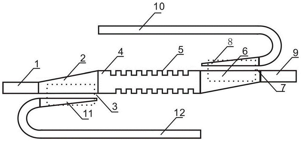
[0043] Such as figure 1 , figure 2 with Figure 4 As shown, silicon-on-insulator (SOI) material with a top silicon thickness of 220 nm and a silicon oxide buried layer of 2 µm is used. After the wafer surface is cleaned, deep ultraviolet lithography or electron beam direct writing lithography is used to obtain silicon etching. Mask, through silicon dry etching, to produce a strip waveguide with a height of 220 nm, in which the width of the single-mode input waveguide and single-mode output waveguide is 600 nm, the width of the multi-mode waveguide is 1100 nm, and the width of the input gradient waveguide is 600 nm Change to 1100 nm, the change length is 100µm, the width of the down graded waveguide is changed from 100 nm to 450 nm, the change length is 100 µm, the interval between the input graded waveguide and the down graded waveguide is 100 nm, the output graded waveguide and the input graded waveguide structure The same, the upper graded waveguide and the lower graded w...


PUM


Abstract

The invention discloses an optical add drop multiplexer based on an antisymmetric multimode waveguide Bragg grating. When being input from a single-mode input waveguide, TE light is converted into a base mode of a multi-mode waveguide when passing through an input gradual change waveguide; the antisymmetric multimode waveguide Bragg grating reversely couples incident light meeting the phase matching condition into one step mode of the multi-mode wave guide; reflecting light is converted into a TE mode of a lower-path single-mode waveguide when passing through a lower-path coupling region; transmission light is output from a single-mode output waveguide through the output gradual change waveguide. Identically, the ET light is input from an upper path single-mode waveguide, an upper-path coupling region converts the TE light into the TE one step mode of the multi-mode waveguide; the antisymmetric multimode waveguide Bragg grating reversely couples the incident light meeting the phase matching conditions into a base mode of the multi-mode waveguide; reflecting light is output from the single-mode output waveguide through the output gradual change waveguide. The optical add drop multiplexer has the advantage that the optical signal add drop multiplexing function is realized, and the optical add drop multiplexer can be applied to an on-chip high-density integrated optical interconnection system.

Description

technical field [0001] The invention relates to an optical signal add-drop multiplexing integrated device, in particular to an optical signal add-drop multiplexer based on an antisymmetric multimode Bragg waveguide grating. Background technique [0002] With the rapid development of integrated circuits, the feature size of transistors continues to decrease, and high-speed information inevitably encounters a series of bottlenecks in terms of speed, bandwidth, and power consumption when transmitting electrical interconnections. On-chip optical interconnection based on silicon optics provides a feasible solution to this technical problem, and the exchange of information will be carried out directly on the optical transmission layer. [0003] As a basic functional device of optical interconnection, optical filter can flexibly realize the separation, add and drop of different signals, and is a very important link in dense wavelength division multiplexing optical network. At pres...

Claims


Application Information

Patent Timeline
Patent Type & Authority Applications(China)
IPC IPC(8): G02B6/293H04J14/02
CPCG02B6/29305G02B6/29334H04J14/0202
Inventor 邱晖晔梁雄苏玉霞赖国忠
Owner LONGYAN UNIV
Learn More