
Display device measuring device simulating structure of human eyes and measuring method

A technology for display devices and measuring devices, which is applied in the direction of photometry, optical performance testing, and spectrum investigation using electrical radiation detectors, which can solve the problems of not being, cannot be weighted, and cannot be satisfied, and achieve the effect of accurate data processing.

Active Publication Date: 2016-08-17
SOUTHEAST UNIV
View PDF5 Cites 19 Cited by
  • Summary
  • Abstract
  • Description
  • Claims
  • Application Information

AI Technical Summary

Problems solved by technology

These traditional luminance meters only measure the brightness of the measured object, which is an objective physical quantity, not the brightness that the human eye can actually perceive.
And the traditional brightness has the following disadvantages: 1. The incident aperture is much larger than the 7mm pupil diameter of the human eye, and the field of view (FOV) is 0.1°, 0.2°, 1° or 2°, which cannot meet the requirements of radiation standards; 2. Usually used V(λ) for matching, cannot be weighted according to the weighting function required by the standard; 3. The position of the entrance pupil is uncertain, usually the rear end of the lens, which cannot really meet the requirements of the 200mm test distance
Human eye simulation has been studied at home and abroad, but few institutions use human eye simulation technology combined with CCD arrays to conduct comprehensive and real-time evaluations of color, brightness, motion blur and other characteristics of display devices.

Method used


Image

  • Display device measuring device simulating structure of human eyes and measuring method
  • Display device measuring device simulating structure of human eyes and measuring method
  • Display device measuring device simulating structure of human eyes and measuring method

Examples


Embodiment Construction

[0028] The present invention will be further described below in conjunction with the accompanying drawings.

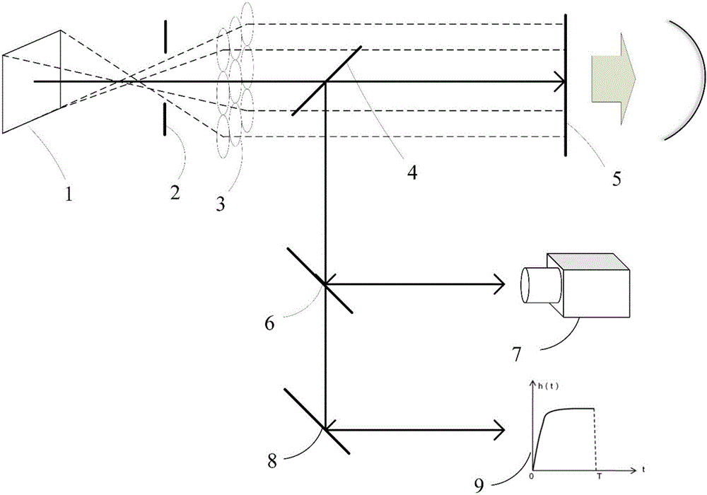
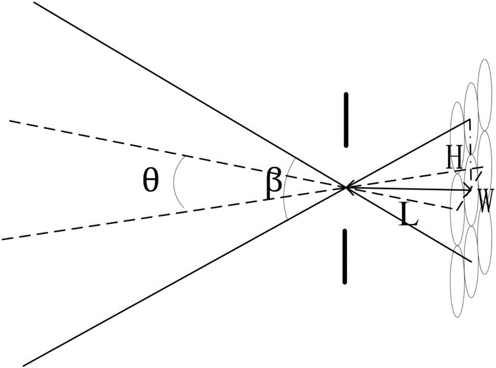
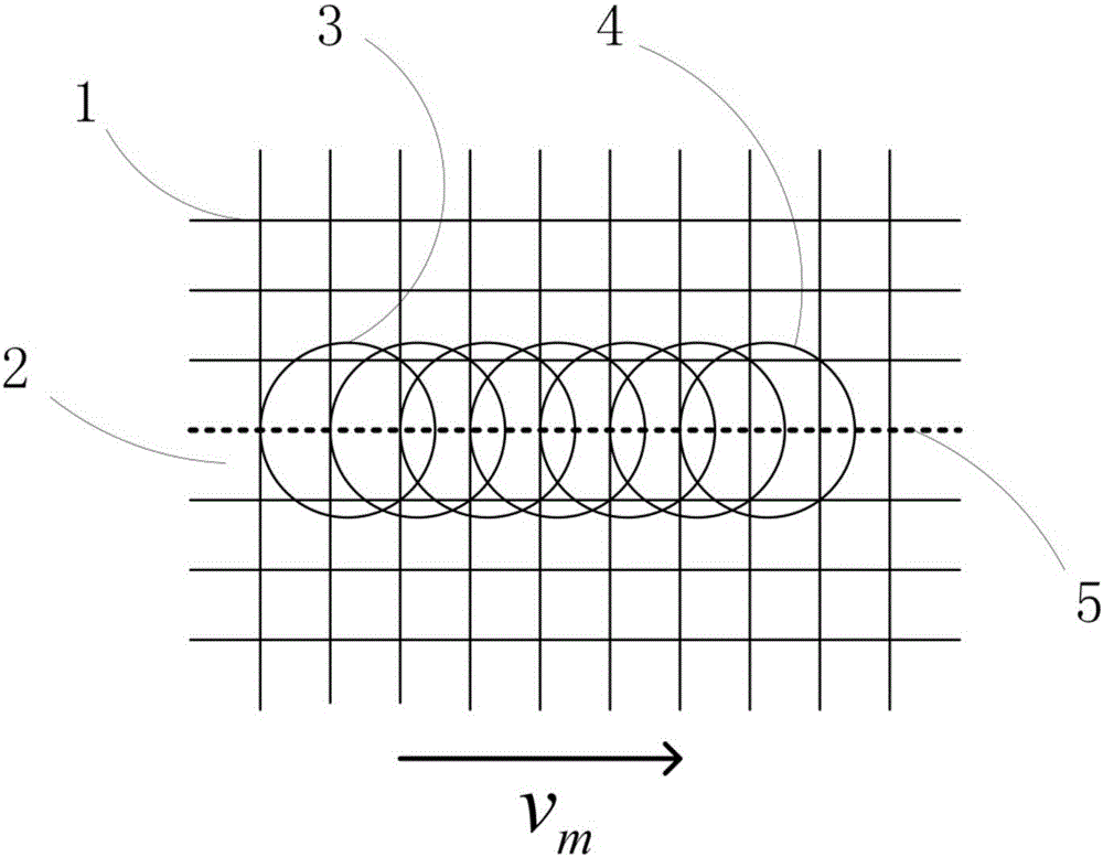
[0029] Such as figure 1 As shown, the present invention includes an optical imaging device, an optical radiation measuring device, and a dynamic testing device. The optical imaging device includes a display device 1, an aperture stop 2, a crystalline lens array 3 of 3×3 specifications, and a first semi-reflective half Lens 4 and CCD array 5. The aperture stop 2 is located on the lens focal plane corresponding to the lens array 3 , and the display device 1 , the stop 2 and the lens array 3 are located on the same horizontal plane. The diameter of the aperture stop 2 is adjustable, which is consistent with the diameter of the pupil of the human eye, and the adjustable range is 3 to 25 mm; the lens array 3 is composed of M×N lens arrays, the length and width of the lenses are the same, and the focal length of the lens is f= 17mm, the curvature of the crystalline lens is...


PUM


Abstract

The invention discloses a display device measuring device simulating the structure of human eyes and a measuring method. By means of an optical system and a software processing system, retinal imaging simulation and optical safe measurement are achieved. The optical system comprises one or two optical imaging devices, a light radiation measuring device and a dynamic measuring device. The software processing system comprises a human eye smooth tracking model, a subjective matching test model, a Photopic deviation model and other human eye visual models. A part of the optical system can finally generate images in human eye retinas by means of the optical imaging device of a simulation human eye structure and the software system simulating the human eye visual models. A light radiation measuring part of the optical system analyzes spectrum distribution needing light measurement through a photoelectric sensor array, and retinal damage can be accurately evaluated according to a retinal damage weight function curve. The measuring method simulating the structure of the human eyes is disclosed and can omnidirectionally evaluate color, brightness, motion blur and other characteristics of a display device in real time.

Description

technical field [0001] The invention relates to a display device measurement device and a measurement method that simulates the human eye structure, and belongs to the field of display device measurement. Background technique [0002] With the rapid development of display technology, measurement methods for display devices have attracted more and more attention. Display evaluation mainly includes brightness, chromaticity, static contrast ratio and dynamic contrast ratio measurement, motion blur, etc. At present, there are many types of luminance meters on the market, including simple luminance meters, spectral radiance meters, optical imaging luminance meters, high-accuracy luminance meters and CCD imaging luminance meters. However, these traditional luminance meters only measure the brightness of the measured object, which is an objective physical quantity, not the brightness that the human eye can actually perceive. And the traditional brightness has the following disadv...

Claims


Application Information

Patent Timeline
IPC IPC(8): G01M11/02G01J1/42G01J3/28
CPCG01J1/42G01J3/28G01M11/02
Inventor 张宇宁屠彦李晓华王保平沈忠文
Owner SOUTHEAST UNIV
Learn More