Refrigerator refrigeration circulation system

A circulation system and freezer technology, applied in the direction of refrigerators, refrigeration components, refrigeration and liquefaction, etc., can solve the problems of increasing the area of ​​the condenser, increasing the filling volume of the refrigeration system, and reducing competitiveness, so as to improve temperature uniformity and increase Heat exchange efficiency and the effect of improving cooling efficiency

Active Publication Date: 2016-08-17
QINGDAO HAIER SPECIAL ICEBOX
View PDF4 Cites 10 Cited by
  • Summary
  • Abstract
  • Description
  • Claims
  • Application Information

AI Technical Summary

Problems solved by technology

[0003] There are two main improvement technologies at present: one is to increase the heat exchange area of ​​the condenser to fully ensure the supercooling degree of the condenser outlet, so that the capillary inlet is all supercooled refrigerant liquid, and the evaporator inlet is throttled through the capillary. The end dryness is reduced, and the liquid filling rate of the evaporator is increased; however, the area of ​​the condenser is increased too much in this way, which increases the difficulty of the process and increases the cost, which reduces the competitiveness of the product
The second is to increase the filling volume of the refrigeration system, which can increase the circulation flow of the system to a certain extent and increase the liquid filling rate in the evaporator, but it is easy to cause the temperature of the return air pipe to be too low, which will have a negative impact on the service life of the compressor

Method used


Image

  • Refrigerator refrigeration circulation system
  • Refrigerator refrigeration circulation system
  • Refrigerator refrigeration circulation system

Examples


Embodiment Construction

[0026] The present invention will be further described in detail below in conjunction with the accompanying drawings and specific embodiments.

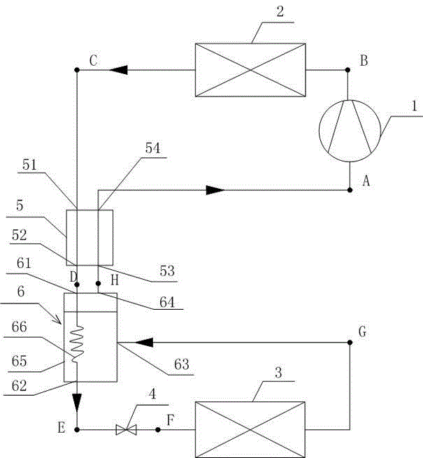
[0027] refer to figure 1 As shown, this embodiment is a schematic flow chart of the refrigeration cycle system of a freezer. The direction of the arrow in the figure indicates the flow direction of the refrigerant, including a compressor 1, a condenser 2, an evaporator 3, and a capillary tube 4. The compressor 1 is connected to the inlet of the condenser 2, and the capillary tube 4 Connect the inlet of the evaporator 3, and set the regenerator 5 and the supercooled liquid receiver 6 after the condenser 2;

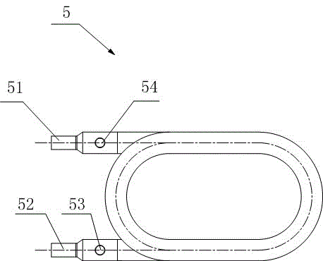
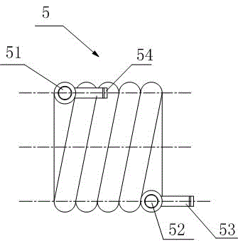
[0028] Such as Figure 2-2 , 2-2 As shown, the regenerator 5 is a regenerator formed by winding or nesting between the outlet pipe of the condenser 2 and the suction pipe of the compressor 1. The regenerator 5 is provided with a high-pressure refrigerant inlet 51 and a high-pressure refrigerant outlet 52 , a low-pressure refrige...


PUM


Abstract

The invention provides a refrigerator refrigeration circulation system. The refrigerator refrigeration circulation system comprises a compressor, a condenser, an evaporator and a capillary pipe, wherein the compressor is connected with the condenser; the capillary pipe is connected with the evaporator; the refrigerator refrigeration circulation system is further provided with a heat regenerator and a supercooling liquid accumulator; the heat regenerator is provided with a high-pressure refrigerant inlet, a high-pressure refrigerant outlet, a low-pressure refrigerant inlet and a low-pressure refrigerant outlet; the supercooling liquid accumulator is provided with a supercooling refrigerant liquid inlet, a supercooling refrigerant liquid outlet, a two-phase refrigerant inlet and a saturated refrigerant vapor outlet; the outlet of the condenser is connected with the high-pressure refrigerant inlet of the heat regenerator; the high-pressure refrigerant outlet is connected with the supercooling refrigerant liquid inlet formed in the supercooling liquid accumulator; the high-pressure refrigerant outlet is connected with the inlet of the evaporator through the capillary pipe; the outlet of the evaporator is connected with the two-phase refrigerant inlet; the saturated refrigerant vapor outlet is connected with the low-pressure refrigerant inlet; and the low-pressure refrigerant outlet is connected with the compressor. By adopting the refrigerator refrigeration circulation system, two-phase heat exchange during the whole evaporation process of the evaporator can be ensured; the heat exchange coefficient of the evaporator is obviously increased; and the heat exchange effect is improved.

Description

technical field [0001] The invention relates to a novel refrigerator refrigeration cycle system. Background technique [0002] The general freezer circulation system is usually mainly composed of compressor, evaporator, condenser and capillary tube. In its plate-tube evaporator, as the refrigerant flows, the refrigerant evaporates continuously, the dryness increases, the wetting circumference of the refrigerant decreases, and the two-phase refrigerant gradually evaporates into saturated or superheated steam. The phase change heat of the refrigerant in the tube gradually becomes the sensible heat heat transfer of the gas, so the heat transfer coefficient of the evaporator will gradually decrease, and its heat transfer capacity will gradually weaken. [0003] There are two main improvement technologies at present: one is to increase the heat exchange area of ​​the condenser to fully ensure the supercooling degree of the condenser outlet, so that the capillary inlet is all sup...

Claims


Application Information

Patent Timeline
Patent Type & Authority Applications(China)
IPC IPC(8): F25B1/00F25B40/02F25B40/06F25B43/00F25B41/06F25B41/37
Inventor 鱼剑琳卞伟丁剑波刘越张天鹏李大伟彭灿俞国新
Owner QINGDAO HAIER SPECIAL ICEBOX
Why Eureka
Try Eureka