
One-sided reed traversing driving mechanism

A traversing mechanism and reed technology are applied in the field of unilaterally driven reed traversing mechanisms to achieve the effect of simple structure

Active Publication Date: 2016-08-17
YANCHENG INST OF IND TECH
View PDF12 Cites 0 Cited by
  • Summary
  • Abstract
  • Description
  • Claims
  • Application Information

AI Technical Summary

Problems solved by technology

Patent CN201120552808.2 discloses a reed traversing mechanism, which realizes the reed's reciprocating motion and left and right traversing motion. The original equipment is slightly changed, but guide rails and other parts are arranged on the left and right sides, which is not suitable for water spraying and air jetting. Shuttle looms, due to their compact size and one-sided weft insertion

Method used


Image

  • One-sided reed traversing driving mechanism
  • One-sided reed traversing driving mechanism
  • One-sided reed traversing driving mechanism

Examples


Embodiment Construction

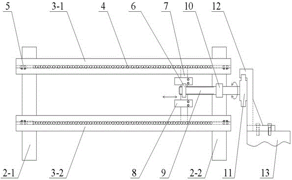
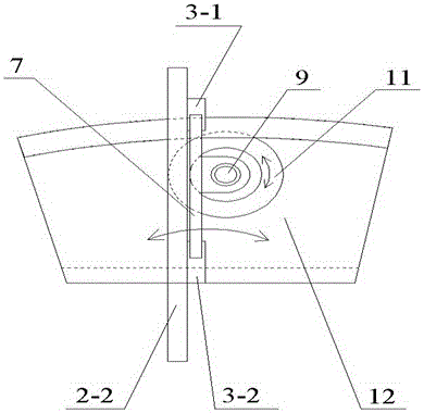
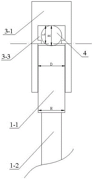
[0022] The embodiments will be further described below in conjunction with the accompanying drawings. Such as figure 1 Shown, install upper and lower reed caps 3-1, 3-2 additionally on the sley feet 2-1 and 2-2 of the shuttleless loom. The shape of the reed hat is as image 3 As shown, it is groove-shaped, and its groove width D is equal to the thickness H of the reed beam 1-1. Such as Figure 5 with figure 1 As shown, the reed 1 is loosely installed between the upper and lower reed caps 3-1 and 3-2, and the reed connector 8 is used to connect the reed and the slide block 7 as one. Two of slide block 7 stretch in the groove of reed cap, loosely dress on the right side between two reed caps, can move left and right along reed cap length direction, also drive steel reed to move sideways simultaneously.

[0023] The left and right movement of slide block 7 is realized in the following way. Such as figure 1 , a drive nut 6 is fixed on the slider 7, a bearing 10 is fixed on ...


PUM


Abstract

The invention discloses a one-sided reed traversing driving mechanism, which comprises sley swords connected with a beating-up mechanism, upper and lower reed caps arranged on the sley swords and a reed connecting piece positioned between the upper and lower reed caps, and is characterized in that a transmission nut is arranged on the reed connecting piece, and a transmission screw rod is connected onto the transmission nut; a transmission gear meshed with an inner gear fixedly arranged on a loom rack is arranged at the other end of the transmission screw rod. When a loom runs, the sley swords swing back and forth to drive the transmission gear and the transmission screw rod to rotate and thus drive a sliding block to move left and right, thereby the reed transverses left and right. The one-sided reed traversing driving mechanism provided by the invention has the advantages of simple structure and one-sided driving, and is suitable for a one-sided weft insertion shuttleless loom.

Description

technical field [0001] The invention relates to a single-side driving reed traverse mechanism, which belongs to the technical field of textile machinery. Background technique [0002] Wide-angle cloth is a kind of industrial cloth, which is derived from ordinary woven plain weave. From a structural point of view, it is also composed of two systems of yarns, but unlike ordinary woven fabrics, the angle between the two systems of yarns is not 90° but other angles (typically 120°). This special structure makes The deformation ability of wide-angle cloth is higher than that of ordinary woven fabric, especially the deformation ability along the vertical direction of the cloth surface is more prominent. [0003] On the other hand, the non-90° included angle between the two systems of yarns makes it difficult to realize weaving on common looms, and the most difficult realization of the weft-beating part is wherein. Patents CN201410257262.6 and CN201420308470.X disclose a kind of ...

Claims


Application Information

Patent Timeline
Patent Type & Authority Applications(China)
IPC IPC(8): D03D49/60D03D49/62
CPCD03D49/60D03D49/62
Inventor 瞿才新姚桂香徐帅杨晓芳
Owner YANCHENG INST OF IND TECH
Learn More