
A new rolling ring assembly structure suitable for old drum equipment

An assembly structure and rolling ring technology, applied in mechanical equipment, hoisting devices, components with teeth, etc., can solve problems such as poor relative strength and hardness, weld fatigue, increased deformation, etc., to reduce maintenance costs , increase the benefits of enterprises, and strengthen the effect of rigidity

Active Publication Date: 2018-09-07
HANGZHOU RECLAIMED WATER TECH CO LTD
View PDF4 Cites 0 Cited by
  • Summary
  • Abstract
  • Description
  • Claims
  • Application Information

AI Technical Summary

Problems solved by technology

[0005] To sum up, the new and old-fashioned technology has the following disadvantages: the rolling ring and the drum body are fixed by welding, and the material of the rolling ring can only choose low-alloy steel with relatively good welding performance, which makes the alloy content of the material of the rolling ring itself Low, direct use, no heat treatment, relatively poor strength and hardness; secondly, in order to strengthen the rigidity of the roller ring section of the drum body, a layer of cladding plate is added to the outer circle of the drum, and it is fixed in the form of welding. And the inner circle of the doubler plate cannot be completely fitted, and there must be a gap after welding. After a long time of operation, the weld will be fatigued, coupled with the existing gap and the lack of rigidity of the material, the degree of deformation will gradually increase until it affects the normal operation of the equipment. running; the sprocket used to fix the chain is directly fixed on the rolling ring by bolts, and the two will inevitably interfere during the operation process, which will bring unstable factors to the smooth operation of the drum body

Method used


Image

  • A new rolling ring assembly structure suitable for old drum equipment
  • A new rolling ring assembly structure suitable for old drum equipment
  • A new rolling ring assembly structure suitable for old drum equipment

Examples


Embodiment Construction

[0029] In order to further understand the contents of the present invention, the present invention will be described in detail in conjunction with the accompanying drawings and examples. The following examples are used to illustrate the present invention, but not to limit the scope of the present invention.

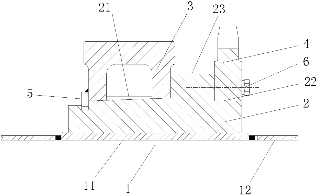
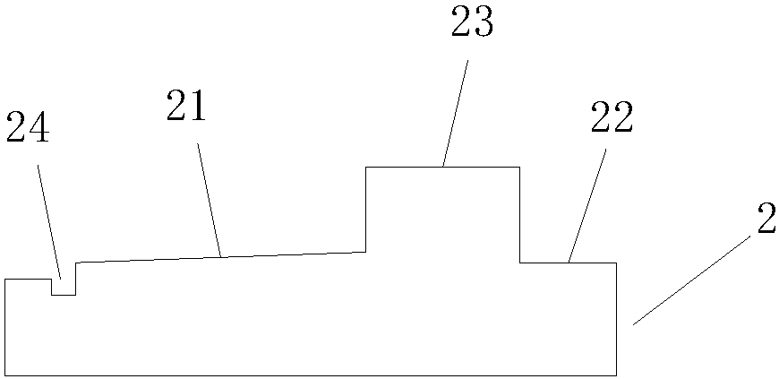
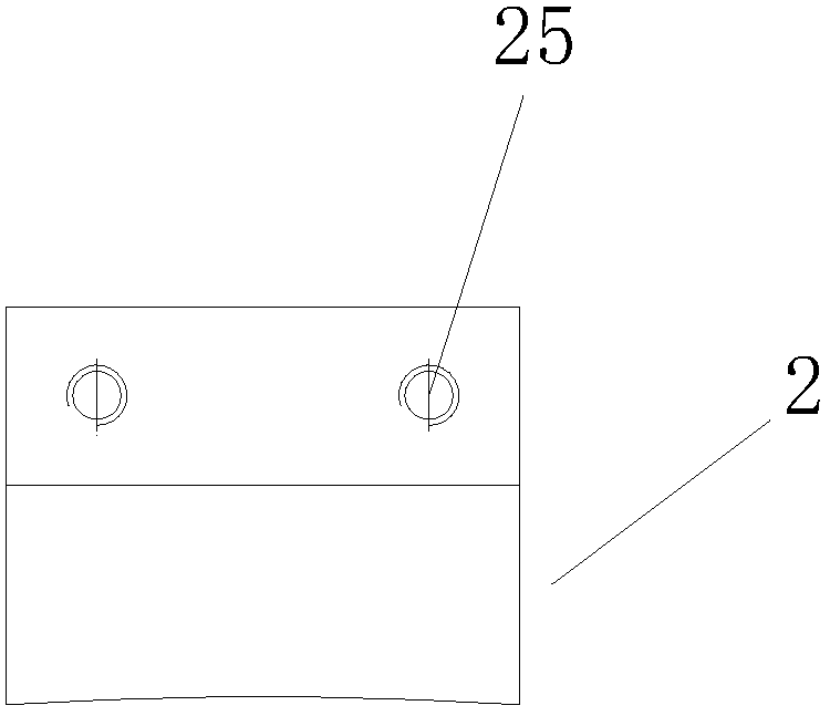
[0030] combine figure 1 , the present invention relates to a new type of rolling ring assembly structure suitable for old drum equipment, including a drum body 1, a rolling ring 3 and a sprocket 4, which also includes a rolling ring spacer 2 and a rolling ring clamping plate 5. The drum body 1 includes a first drum body 11 in the middle of the drum body and a second drum body 12 at two ends, the thickness of the first drum body 11 is thicker than that of the second drum body 12, and the circumference of the two ends of the first drum body 11 Grooves are respectively opened in the directions, and the first drum body 11 is welded to the second drum body 12 at both ends thro...


PUM


Abstract

The invention relates to a novel rolling ring assembly structure suitable for drumaging equipment. The rolling ring assembly structure comprises a drum body, a rolling ring and a chain wheel, and is characterized by also comprising rolling ring cushion blocks and a rolling ring snap-gauge, wherein a plurality of rolling ring cushion blocks are uniformly distributed in a circle on the top circle of the drum body; a slope for installing the rolling ring and a plane for installing the chain wheel are formed on the rolling ring cushion blocks; a step is arranged on one side of the slope near the plane, a groove is arranged on the other side of the slope far from the plane, the rolling ring snap-gauge is arranged in the groove, the rolling ring and the slope are arrangedthrough circular conical surface interference fit connection, and the chain wheel is fixed to one side face of the step through bolted connection. The rolling ring assembly structure overcomes the defects of the traditional drumaging rolling ring that the structure and material are unreasonable and liable to cause deformation and out-of-roundness of the drum body.

Description

technical field [0001] The invention relates to an old drum equipment, in particular to a new rolling ring suitable for the old drum equipment [0002] structure. Background technique [0003] The molecular chain of alkali cellulose without aging process is very long. If it is made into viscose, the viscosity will be too high, resulting in difficulty in spinning. The method to reduce the viscosity is to use the principle of oxidative depolymerization to reduce the molecular chain length of alkali cellulose. Alkali cellulose is kept at a constant temperature (18°C-60°C) for a certain period of time (1h-60h), oxidatively degraded in the air, and the molecular chain becomes shorter. This is the aging process of alkali cellulose. [0004] At present, there are mainly two types of equipment that can meet this process on the market. The traditional aging process is to slowly transport raw materials in the aging box by means of a conveyor belt. Its obvious disadvantages are inter...

Claims


Application Information

Patent Timeline
Patent Type & Authority Patents(China)
IPC IPC(8): C08B1/10F16D1/06F16H55/30
CPCC08B1/10F16D1/06F16H55/30F16H57/0025
Inventor 胡斌杰周志林方园陈油亮
Owner HANGZHOU RECLAIMED WATER TECH CO LTD
Learn More